Index - 1
62-12023
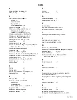
INDEX
A
Accessing Alarm Messages
Alarm Display
C
Cab Command, Road Only
Display
Introduction
Keypad
Unit operating LEDs
Caution Statements
Charging the Refrigeration System
Checking the Charge
Installing a Complete Charge
Checking and Replacing Filter-Drier
Checking for Non-Condensables
Checking the EEPROM Version
Clearing Past Alarm Messages
Compressor
Compressor Oil Type
Compressor Pressure Regulating Valve (CPR)
Adjusting
Compressor Reference Data
Condenser Coil
Condenser Coil Cleaning
Condenser Pressure Control Switch (HP2)
Condenser Pressure Control Valve (HGS2)
Condensing Section
Connecting Manifold Gauge/Hose Set
Control System
Cooling Mode
D
Defrost
Defrost Cycle
Defrost Termination Thermostat (DTT)
Diagnostic Tool
E
Electrical Data
Evacuation and Dehydration
General
Preparation
Procedure for Complete System
Evaporator Coil
Evaporator Coil Cleaning
Evaporator Section
F
First Aid
Frozen Mode
G
General Description
General Safety Notices
H
Heating Mode
High Pressure Switch (HP1)
Hot Gas Solenoid Valve (HGS1)
I
Installing R-404a Manifold Gauge Set
L
Low Battery Voltage Alarms
Low Pressure Switch (LP)
M
Maintenance Precautions
Malfunction Condenser Pressure Regulating Valve
Microprocessor
Minimum Off Time
Modification of Functional Parameters
Road Only Units
N
Notice Statements
O
Operating Precautions
P
Preparing Manifold Gauge/Hose Set For Use
Preventative Maintenance
Pumping Down or Removing Refrigerant Charge
Q
Quench Valve (BPV)
R
Receiver
Refrigerant Circuit
Refrigerant Circuit During Cooling
Refrigerant Circuit During Heat And Defrost
Summary of Contents for Integra 35X
Page 2: ......
Page 8: ......
Page 12: ......
Page 68: ......
Page 69: ...wiring schematics ...
Page 70: ......
Page 71: ...wiring schematics ...
Page 72: ......
Page 73: ...wiring schematics ...
Page 74: ......
Page 75: ...wiring schematics ...
Page 76: ......
Page 79: ......


