5-5
62-12023
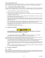
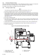
Removing the Refrigerant Charge
Connect a refrigerant recovery system [Carrier P/N MVS-115-F-L-CT (115V) or MVS-240-F-L-CT (240V)] to the unit to
remove refrigerant charge. Refer to instructions provided by the manufacturer of the refrigerant recovery system.
5.3.1
Pumping the Unit Down If Standby Is Available
To service the moisture
l
iquid indicator, liquid line check valve, expansion valve, quench valve, evaporator
coil,
compressor pressure regulating valve, or suction bypass valve, pump the refrigerant into the high side as fol-lows:
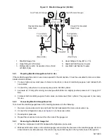
1. Attach manifold gauge set to standby compressor service valves.
2. Start the unit and run in standby cooling mode for 10 to 15 minutes.
3. Frontseat the king valve. Place the emergency switch in the OFF position when the suction reaches a posi-
tive pressure of 1.0 psig (0.01 Bar).
4. Frontseat the standby suction service valve. The refrigerant will be trapped between the standby compres-
sor suction service valve and the liquid line valve.
5. Before opening up any part of the system, a slight positive pressure should be indicated on the pressure
gauge. If a vacuum is indicated, emit refrigerant by cracking the liquid line valve momentarily to build up a
slight positive pressure.
6. When opening up the refrigerant system, certain parts may frost. Allow the part to warm to ambient tempera-
ture before dismantling. This avoids internal condensation which puts moisture in the system.
7. After repairs have been made, perform a refrigerant leak check (refer to
), and evacuate and
dehydrate the low side (refer to
).
8. Check refrigerant charge (refer to
5.4
Refrigerant Leak Checking
CAUTION
!
Refrigerant R-404A is a blend. Charging as a vapor will change the properties of the refrigerant.
Only liquid charging through the king valve is acceptable.
NOTE
Only refrigerant 404A should be used to pressurize the system. Any other gas or vapor will contami-
nate the system which will require additional purging and evacuation of the system.
A refrigerant leak check should always be performed after the system has been opened to replace or repair a com-
ponent. To check for leaks in the refrigeration system, perform the following procedure:
1. The recommended procedure for finding leaks in a system is with an electronic leak detector (Carrier Tran-
sicold P/N 07-00295-00). Testing joints with soapsuds is satisfactory only for locating large leaks.
2. If system is without refrigerant or the low side has been pumped down, charge with refrigerant R-404A to build
up pressure between 30 and 50 psig (2 to 3.4 Bar). Remove refrigerant cylinder and leak check all connec-
tions.
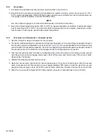
3. Remove test refrigerant using a refrigerant recovery system and repair any leaks. Evacuate and dehydrate
the unit or low side as applicable (refer to
).
5.5
Evacuation and Dehydration
5.5.1
General
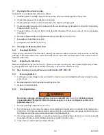
Moisture can seriously damage refrigerant systems. The presence of moisture in a refrigeration system can have
many undesirable effects. The most common are copper plating, acid sludge formation, “freezing-up” of metering
devices by free water, and formation of acids, resulting in metal corrosion.
Summary of Contents for Integra 35X
Page 2: ......
Page 8: ......
Page 12: ......
Page 68: ......
Page 69: ...wiring schematics ...
Page 70: ......
Page 71: ...wiring schematics ...
Page 72: ......
Page 73: ...wiring schematics ...
Page 74: ......
Page 75: ...wiring schematics ...
Page 76: ......
Page 79: ......

