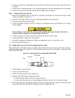
62-12023
5-6
5.5.2
Preparation
1. Evacuate and dehydrate only after pressure leak test (refer to
).
2. Essential tools to properly evacuate and dehydrate any system include a good vacuum pump (5 cfm =
8m
3
H volume displacement, P/N07-00176-01) and a good vacuum indicator such as a thermocouple vac-
uum gauge (vacuum indicator). (Carrier P/N 0700414-00).
NOTE
Use of a compound gauge is not recommended because of its inherent inaccuracy.
3.
Keep the ambient temperature above 60°F (15.6°C) to speed evaporation of moisture. if ambient tempera-
ture is lower than 60°F (15.6°C), ice might form before moisture removal is complete. Heat lamps or alter-
nate sources of heat may be used to raise system temperature.
5.5.3
Evacuation and Dehydration - Complete System
1. Remove refrigerant using a refrigerant recovery system.
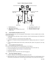
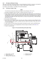
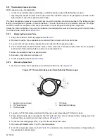
2. The recommended method to evacuate and dehydrate the system is to connect three evacuation hoses to
the vacuum pump and refrigeration unit as shown in
(do not use standard service hoses as they
are not suited for evacuation purposes). Connect an evacuation manifold with special evacuation hoses to
the vacuum pump, to the electronic vacuum gauge and to the refrigerant recovery system.
3. Test the evacuation system for leaks by backseating the unit service valves, and drawing a deep vacuum
with the vacuum pump and gauge valves open. Shut off the pump and check to see if the vacuum holds.
Repair leaks if necessary.
4. Midseat the refrigerant system service valves.
5. Open the vacuum pump and electronic vacuum gauge valves, if they are not already open. Start the vacuum
pump. Evacuate unit until the electronic vacuum gauge indicates 2000 microns. Close the electronic vacuum
gauge and vacuum pump valves. Shut off the vacuum pump. Wait a few minutes to be sure the vacuum holds.
6. Break the vacuum with refrigerant 404A. Raise system pressure to approximately 2 psig (0.14 Bar).
Summary of Contents for Integra 35X
Page 2: ......
Page 8: ......
Page 12: ......
Page 68: ......
Page 69: ...wiring schematics ...
Page 70: ......
Page 71: ...wiring schematics ...
Page 72: ......
Page 73: ...wiring schematics ...
Page 74: ......
Page 75: ...wiring schematics ...
Page 76: ......
Page 79: ......

