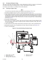
5-9
62-12023
- - - - -
5.7
Checking for Non-Condensables
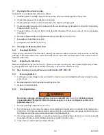
To check for non-condensables, proceed as follows:
1. Stabilize system to equalize pressure between the suction and discharge side of the system.
2. Check temperature at the condenser and receiver.
3. Check pressure at the king valve access port or the liquid line charging port.
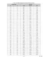
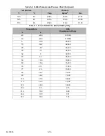
4. Check saturation pressure as it corresponds to the condenser/receiver temperature using the Temperature-
Pressure Chart,
5. If gauge reading is 3 psig (0.2 Bar) or more than the calculated P/T pressure in step 4, non-condensables
are present.
6. Remove refrigerant using a refrigerant recovery system (refer to
7. Evacuate and dehydrate the system
8. Charge the unit (refer to
5.8
Checking and Replacing Filter Drier
5.8.1
Checking Filter Drier
Check for any obstruction of the filter drier by feeling the inlet and outlet connections of the liquid line on the filter
cartridge. If the temperature of the outlet connection seems lower than the temperature of the inlet connection,
replace the filter drier.
5.8.2
Replacing the Filter Drier
Remove refrigerant charge (see
). Remove the drier mounting clip, then replace the filter drier. Follow-
ing drier replacement, evacuate and recharge unit (refer to
).
5.9
High, Condenser, and Low Pressure Control Switch (HP1, HP2, LP)
5.9.1
Removing Switches
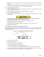
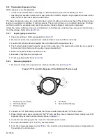
1. A schraeder valve is located under each switch to allow removal and installation without removing the refrig-
erant charge.
2. Remove switch and test in accordance with
3. Replace or reinstall switch.
5.9.2
Checking Switches
WARNING
!
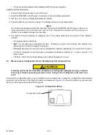
Do not use a nitrogen cylinder without a pressure regulator (see
). Cylinder pressure
is approximately 2350 psi (160 Bar).Do not use oxygen in or near a refrigerant system as an
explosion may occur.
1. Remove switch as outlined in
.
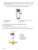
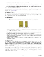
2. For high pressure and condenser pressure control switches connect switch to a cylinder of dry nitrogen (see
). For the low pressure switch, also connect to a vacuum pump and gauge. Test both low and
high pressure switches using method described in the following steps.
3. Set nitrogen pressure regulator or vacuum pump and gauge higher than cut-out or cut in point on switch
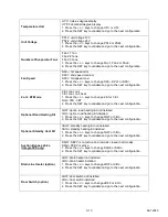
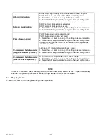
being tested. Pressure switch settings points are provided in
.
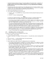
4. Close valve on cylinder and open bleed-off valve.
Summary of Contents for Integra 35X
Page 2: ......
Page 8: ......
Page 12: ......
Page 68: ......
Page 69: ...wiring schematics ...
Page 70: ......
Page 71: ...wiring schematics ...
Page 72: ......
Page 73: ...wiring schematics ...
Page 74: ......
Page 75: ...wiring schematics ...
Page 76: ......
Page 79: ......

