5-13
62-12023
7. Note the temperature of the suction gas at the expansion valve bulb.
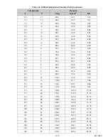
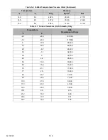
8. Subtract the saturation temperature determined in Step 6 from the average temperature measured in Step
7. The difference is the superheat of the suction gas. Refer to
for superheat setting.
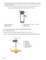
9. If required adjust superheat by turning the adjusting screw located under the cap on the side of the valve.
5.12.3
Checking The TXV Orifice Strainer
). Remove the bottom connection on the TXV. Remove the strainer and
check for obstruction or damage. Clean or replace strainer assembly and tighten connection at bottom of valve.
Evacuate unit (refer to
5.13 Compressor Oil Type
The compressor(s) are supplied with CARRIER POLYESTER (POE) oil. Ensure compressor is marked with a fac-
tory sticker indicating the correct oil has been installed. Oils of PAG type are strictly incompatible with the operation
of this unit, never use an oil other than that approved by CARRIER.
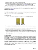
5.14 Diagnostic Tool
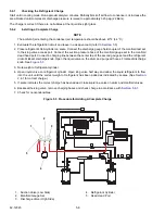
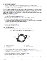
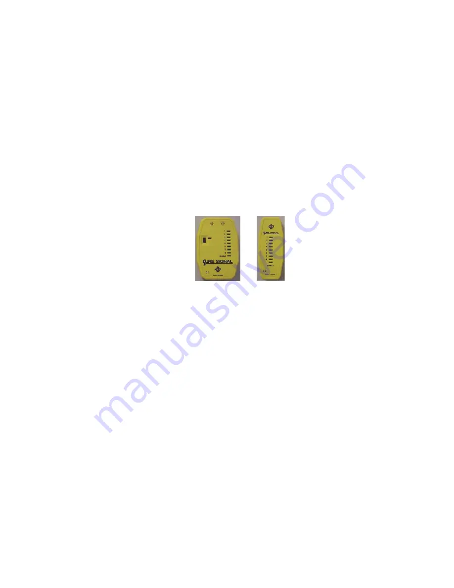
Figure 5.8 Cab Command/Cab Command Two Diagnostic Tool (CTD P/N 07-00440-00)
1. Testing a cab command cable that is already installed on the unit and routed into the truck cab requires the
use of both pieces of the diagnostic tool.
2. Unplug the cab command cable from the microprocessor and also from the back of the cab command module.
3. Plug one end of the cable into the primary tool and the other end into the remote tool.
4. Begin the test by turning on the power switch and observing the sequence of green lights. As each circuit is
tested, the corresponding light is illuminated. If a fault is found in the cable, the light that corresponds to that
particular circuit is not illuminated.
5. To test a cable that is not installed on a unit, simply plug each end of the cable into the primary tool and per-
form the test as above.
5.15 Microprocessor
Although there is less danger of electrical static discharge (ESD) damage in the outdoor environment, where the
processor is likely to be handled, proper board handling techniques should be stressed. Boards should always be
handled by their edges, in much the same way one would handle a photograph. This not only precludes the possi-
bility of ESD damage, but also lowers the possibility of physical damage to the electronic components. Although
the microprocessor boards are fairly rugged when assembled, they are more fragile when separated and should
always be handled carefully.
When welding is required on the unit frame, or on the front area of the trailer, ALL wiring to the microprocessor
MUST be disconnected.When welding is performed on other areas of the truck and van, the welder ground con-
nection MUST be in close proximity to the area being welded. It is also a good practice to remove both battery
cables before welding on either the unit frame or the truck to prevent possible damage to other components such
as the alternator and voltage regulator.
5HPRWH7RRO
3ULPDU\7RRO
Summary of Contents for Integra 35X
Page 2: ......
Page 8: ......
Page 12: ......
Page 68: ......
Page 69: ...wiring schematics ...
Page 70: ......
Page 71: ...wiring schematics ...
Page 72: ......
Page 73: ...wiring schematics ...
Page 74: ......
Page 75: ...wiring schematics ...
Page 76: ......
Page 79: ......

