T-372
7–26
7.22 Economizer Expansion Valve
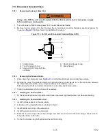
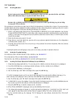
The economizer expansion valve (see
) is an automatic device that maintains constant superheat of
the refrigerant gas leaving at the point of bulb attachment, regardless of suction pressure.
Unless the valve is defective, it seldom requires maintenance other than periodic inspection to ensure that the ther
-
mal bulb is tightly secured to the suction line and wrapped with insulating compound.
NOTE
The economizer expansion valve is a hermetic valve, it does not have adjustable superheat.
Figure 7.17 Economizer Expansion Valve
7.22.1
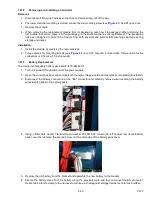
Removing the Economizer Expansion Valve
1. Pump down the compressor (see
) and frontseat both suction and discharge valves. If unit is not
equipped with service valves, evacuate unit. See
.
2. Turn unit power off and remove power from the unit.
3. Remove cushion clamps located on the inlet and outlet lines.
4. Remove insulation (Presstite) from the expansion valve bulb.
5. Unstrap the bulb, located on the economizer line.
6. Remove the valve. The preferred method of removing the valve is to cut the connection between the brazed
section and the valve, using a small tube cutter. Remove valve. Alternatively, use a wet rag to keep valve
cool. Heat inlet and outlet connections to valve body and remove valve.
7. Clean the valve stem with a mild cleaner, if necessary.
7.22.2
Installing the Economizer Expansion Valve
1. The economizer expansion valve should be wrapped in a soaked cloth for brazing.
2. Braze the inlet connection to the inlet line.
3. Braze the outlet connection to the outlet line.
4. Reinstall the cushion clamps on the inlet and outlet lines.
5. Replace the filter drier. See
6. Evacuate to 500 microns by placing vacuum pump on liquid line and suction service valve.
7. Check economizer expansion valve superheat (see
).
7.23 Troubleshooting P6-7 (DUV)
A failed digital unloader valve (DUV), which is normally closed, or an internal seal failure of the compressor can
result in the unit running continually in the fully loaded mode causing it to undershoot its setpoint temperature.
Both of these conditions can be evaluated by running pre-trip test P6-7. When running P6-7, the controller is look
-
ing for the differences in pressure and current draw between loaded mode and unloaded mode to make a judg
-
ment. If there are no differences, then it will show fail.
Inlet
Outlet

