4–19
T-372
4.6.6
Thermistor Format (dCF04)
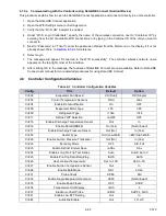
The user may configure the format in which the thermistor readings are recorded. The short resolution is a 1 byte
format and the long resolution is a 2 byte format. The short requires less memory and records temperature with
variable resolutions depending on temperature range. The long records temperature in 0.01°C (0.02°F) steps for
the entire range.
4.6.7
Sampling Type (dCF05 & dCF06)
Three types of data sampling are available: average, snapshot and USDA. When configured to average, the aver
-
age of readings taken every minute over the recording period is recorded. When configured to snapshot, the sen
-
sor reading at the log interval time is recorded. When USDA is configured, supply and return temperature readings
are averaged and the three USDA probe readings are snapshot.
4.6.8
Alarm Configuration (dCF07 - dCF10)
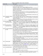
USDA and cargo probe alarms may be configured to OFF, ON or AUTO.
If a probe alarm is configured to OFF, the alarm for this probe is always disabled.
If a probe alarm is configured to ON, the associated alarm is always enabled.
If the probes are configured to AUTO, they act as a group. This function is designed to assist users who keep the
DataCORDER configured for USDA recording, but do not install the probes for every trip. If all the probes are dis
-
connected, no alarms are activated. As soon as one of the probes is installed, all of the alarms are enabled and the
remaining probes that are not installed will give active alarm indications.
4.6.9
Stored Temperature Display (Scrollback)
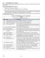
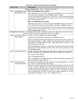
The DataCORDER records temperatures from the supply sensor, return sensor, P1, P2, P3 and C4 cargo sensors.
The temperatures are recorded every hour.
Displaying Stored Temperatures
1. Press the ALT. MODE key on the keypad.
2. Use the Arrow keys until “dCdSP” is displayed.
3. Press the ENTER key.
4. Use the Arrow keys to toggle through S (supply), R (Return), P1, P2, P3 and C4 (Cargo) sensors.
5. Press the ENTER key and a temperature value will appear in the right window and 1 (with sensor designa
-
tion) will appear in the left window to signify the temperature displayed is the most recent reading. Each
press of the down Arrow key displays the temperature one hour earlier.
6. Press the ENTER key to alternate between sensors and times / temperatures. And use Arrow keys for scrolling.
4.6.10
DataCORDER Power Up
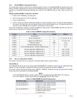
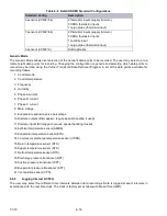
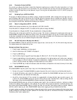
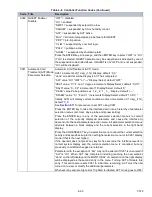
The DataCORDER may be powered up in any one of the following methods:
1.
Normal AC power:
The DataCORDER is powered up when the unit is turned on via the Stop-Start switch.
2.
Controller DC battery pack power:
If a battery pack is installed, the DataCORDER will power up for commu
-
nication when the user presses the battery key.
3.
Real Time Clock demand:
If the controller is equipped with a charged battery pack and AC power is not
present, the DataCORDER will power up when the real time clock indicates that a data recording should
take place. When the DataCORDER is finished recording, it will power down.
During DataCORDER power-up, while using battery-pack power, the controller will perform a hardware voltage
check on the battery. If the hardware check passes, the controller will energize and perform a software battery volt
-
age check before DataCORDER logging. If either test fails, the real time clock battery power-up will be disabled
until the next AC power cycle. Also, DataCORDER temperature logging will be prohibited until that time.
An alarm will be generated when the battery voltage transitions from good to bad indicating that the battery pack
needs recharging. If the alarm condition persists for more than 24 hours on continuous AC power, it indicates that
the battery pack needs replacement.

