7–19
T-372
c. Reconnect the remaining good wiring pairs to their original connections.
d. The unit will fail the PTI test P1-0 at the next pre-trip inspection. Repair action can be taken at that time.
6. If the unit is empty, replace the faulty heater:
WARNING
!
Before servicing the unit, make sure the circuit breakers (CB-1 & CB-2) and start-stop switch
(ST) are in the OFF position and the power plug is disconnected.
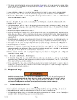
a. With the heater pair identified, remove the upper back panel inside the container.
b. Identify the center point connection for the heater pair (black wiring from heaters) either against the unit
back wall or in the wiring loom.
c. Cut the splice to separate the two heaters.
d. Carry out a Megger check on the two heaters in the same way as for units with heater panel. Replace
any heater where the Megger readings are < 1 Mohms.
NOTE
If all heaters are above the acceptable limit with the wiring disconnected, then this indicates that the
fault was in one or more of the wire splices that were removed.
e. Remove the hold-down clamp securing the heater(s) to the coil.
f. Verify that the heaters are not hot before handling them.
g. Lift the bent end of the heater (with the opposite end down and away from the coil). Move the heater to
the side enough to clear the heater end support and remove.
h. To install heater, reverse steps.
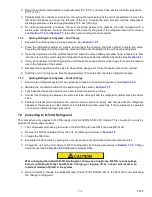
i. Reconnect all wiring using new splices and heat shrink where needed. The heat shrink MUST have a
'melt-able' liner to ensure that the connections are properly sealed when shrunk. This can be seen as a
'Ring' of melt liner pushed from under the heat shrink at each end of the shrink tube.
NOTE
Failure to use melt liner heat shrink allows moisture to 'wick' up under the heat shrink and cause a
leakage path.
7.17 Evaporator Fan and Motor Assembly
The evaporator fans circulate air throughout the container by pulling air in at the top of the unit. The air is forced
through the evaporator coil where it is either heated or cooled and then discharged out the bottom of the refrigera
-
tion unit into the container. The fan motor bearings are factory lubricated and do not require additional grease.
7.17.1
Replacing the Evaporator Fan Assembly
WARNING
!
Always turn OFF the unit circuit breakers (CB-1 & CB-2) and disconnect main power supply
before working on moving parts.
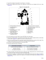
1. Remove the access panel by removing the mounting bolts and TIR locking device. Reach inside of the unit
and remove the Ty-Rap securing the wire harness loop. Disconnect the connector by twisting to unlock and
pulling to separate.
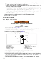
2. Loosen the four 1/4-20 clamp bolts that are located on the underside of the fan deck at the sides of the fan
assembly. Slide the loosened clamps back from the fan assembly.
3. Slide the fan assembly out from the unit and place on a sturdy work surface.


