4–1
T-372
SECTION 4
MICROPROCESSOR
4.1 Temperature Control Microprocessor System
The temperature control Micro-Link 5 microprocessor system consists of a control module (controller), display
module, keypad and interconnecting wiring. The controller houses the temperature control software and the Data
-
CORDER software. The temperature control software functions to operate the unit components as required to pro
-
vide the desired cargo temperature and humidity. The DataCORDER software functions to record unit operating
parameters and cargo temperature parameters for future retrieval. Coverage of the temperature control software
. Coverage of the DataCORDER software is provided in
4.1.1
Control Module
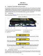
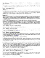
The control module (see
) is fitted with the Micro-Link 5 controller, power connectors, a micro USB port
and short range wireless connectivity.
Figure 4.1 Control Module
1) Micro-Link 5 Controller / DataCORDER Module
2) Controller Power Connector
3) Fuses (7.5A)
4) Device Power Connector
5) Micro USB Port
6) Mounting Screw
- - - - -
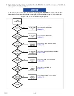
CAUTION
!
Do not remove wire harnesses from circuit boards unless you are grounded to the unit frame
with a static safe wrist strap or equivalent static drain device.
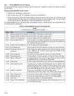
CAUTION
!
Remove the controller module and unplug all connectors before performing any arc welding
on any part of the container.
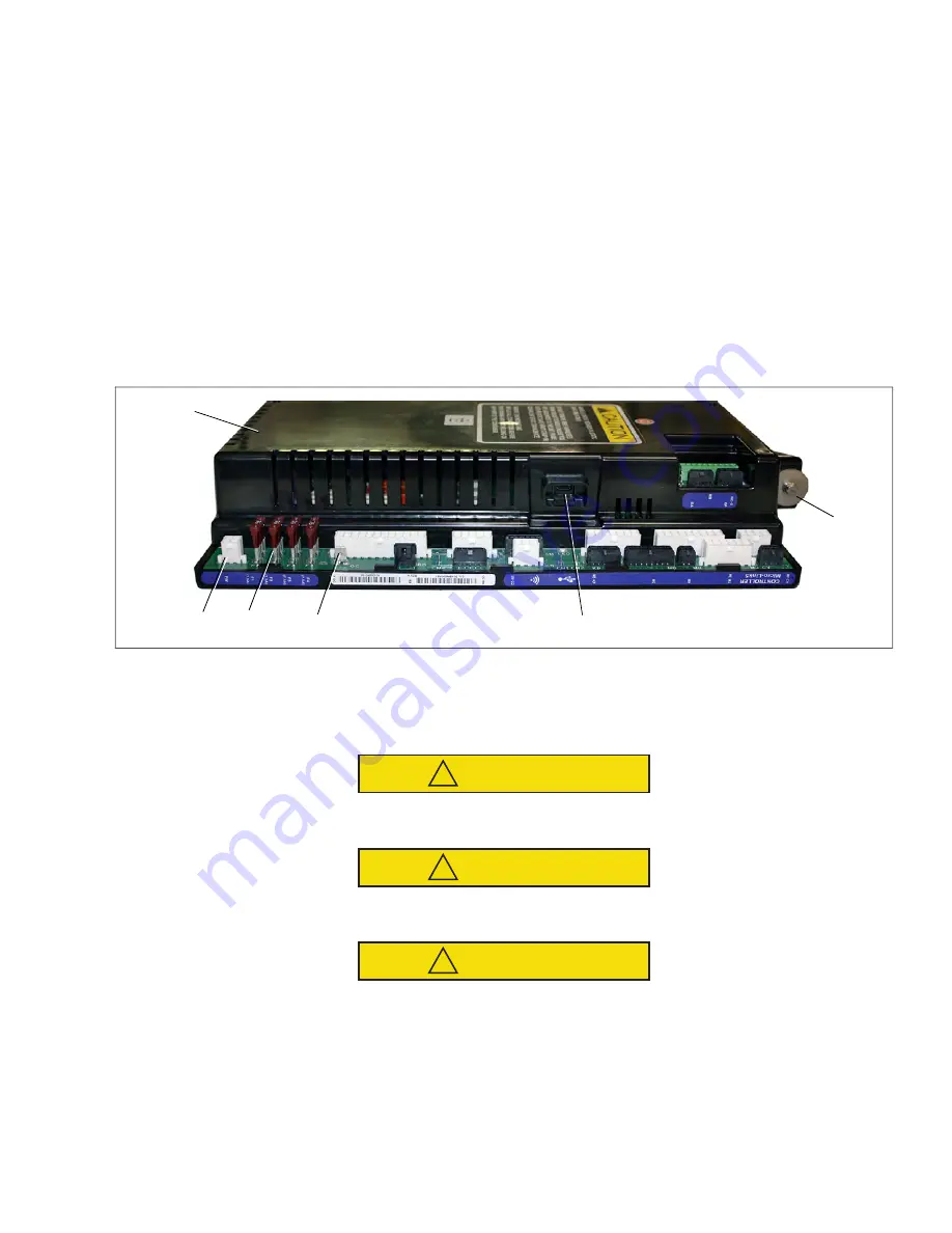
CAUTION
!
When disconnecting connectors from the controller, press the latch tab prior to pulling out the
connector. Damage may occur if latch tab is not pressed in prior to removing the connector.
NOTE
Do not attempt to service the controller modules. Breaking the seal will void the warranty.
4.1.2
Display Module and Keypad
The display module and keypad are mounted on the control box door and serve to provide user access and read
-
outs for both of the controller functions: temperature control and DataCORDER. The functions are accessed by
keypad selections and viewed on the display module.
6
1
3
5
2
4


