5–29
62-11785
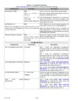
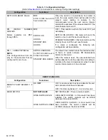
BATT CHARGER
(Applicable to unit - not lift gate -
battery charger only.)
NO TEMP SENSOR
WITH TEMP SENSOR
NO TEMP SENSOR = Use this setting when the
battery charger does not have the temperature
sensor wire.
WITH TEMP SENSOR = Use this setting when the
battery charger does have the temperature sensor
wire (connected to the battery positive post).
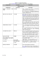
SET DATE AND TIME
Indicates to the main microprocessor the current date and time. Refer to
for instructions on entering the date and time.
NOTE: Date and Time may also be configured under “Unit Identification”.
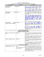
STANDBY STARTUP DELAY
OFF
5 Seconds
10 Seconds
15 Seconds
20 Seconds
RANDOM
Indicates to the microprocessor the delay for this
unit when starting in standby.
This setting is used when multiple units are on the
same line to stagger the occurrence of high inrush
current in situations such as restart after a power
loss.
If RANDOM is chosen a random time between 0
and 120 seconds will be used. “UNIT WILL START
IN XX SECONDS” will display during the count
down period.
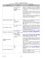
SUCTION PRESSURE
30 PSIG (2.0 BAR)
0 - 50 psig (0 to 3.4 bar)
[in 1 psig (0.1 bar)
increments]
Pressure to maintain if discharge pressure
transducer is opened or shorted.
STANDBY MAX GEN AMPS
22A
10 TO 35 in 0.5A
increments
Indicates to the microprocessor the maximum
allowable amperage in Electric operation. USE
FACTORY DEFAULT SETTING ONLY. DO NOT
OPERATE UNIT WITH DIFFERENT SETTING.
SUPPLY AIR LIMIT FOR S/S
-2.7° to -21.6°F (-1° to -
12°C) in 0.5°F or °C
increments.
DEFAULT: -21.6°F
(-12°C)
Value to be used to calculate the lowest allowable
supply air temperature, when in Start-Stop
Operation, in accordance with the formula “Setpoint
+ this
value = coldest allowable supply air temperature”.
For example: Fahrenheit: if the setpoint is 35°F and
the Configuration value is set at -10°F the
calculation is 35 + (-10) = 25°F lowest allowed
supply air temperature.
Celsius: if the setpoint is 2°C and the Configuration
value is set at -6°C the calculation is 2 + (-6) = -4°C
lowest allowed supply air temperature.
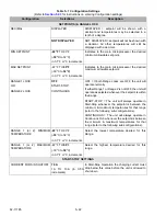
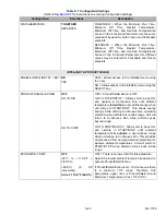
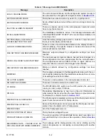
Table 5–1 Configuration Settings
(Refer to
Section 5.2.3
for instructions on entering Configuration settings)
Configuration
Selections
Description
Summary of Contents for VECTOR 8100
Page 2: ......
Page 4: ......
Page 12: ...62 11785 viii ...
Page 16: ...62 11640 12 ...
Page 18: ...62 11785 ...
Page 24: ...62 11785 1 6 1 3 SAFETY DECALS ...
Page 25: ...1 7 62 11785 ...
Page 26: ...62 11785 1 8 ...
Page 27: ...1 9 62 11785 ...
Page 28: ...62 11785 1 10 ...
Page 30: ...62 11785 ...
Page 50: ...62 11785 ...
Page 82: ...62 11785 ...
Page 96: ...62 11785 4 14 ...
Page 98: ...62 11785 ...
Page 129: ...5 31 62 11785 ...
Page 130: ...62 11785 5 32 ...
Page 134: ...62 11785 6 4 ...
Page 138: ...62 11785 ...
Page 230: ...62 11785 ...
Page 271: ...8 41 62 11785 ...
Page 272: ...62 11785 8 42 ...
Page 274: ...62 11785 ...
Page 286: ......
Page 287: ......
Page 288: ...62 11785 10 8 ...
Page 292: ......
Page 293: ......


