62-11785
5–30
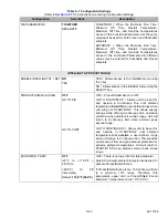
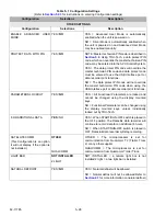
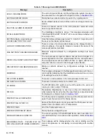
SUPPLY AIR LIMIT FOR CONT -2.7° to -21.6°F (-1° to -
12°C) (in 0.5°F or °C
increments)
DEFAULT: -4.5°F
(-2.5°C)
Value to be used to calculate the lowest allowable
supply air temperature, when in Continuous
Operation, in accordance with the formula “Setpoint
+ this value = coldest allowable supply air
temperature”.
For example: Fahrenheit: if the setpoint is 35°F and
the Configuration value is set at -10°F the
calculation is 35 + (-10) = 25°F lowest allowed
supply air temperature.
Celsius: if the setpoint is 2°C and the Configuration
value is set at -6°C the calculation is 2 + (-6) = -4°C
lowest allowed supply air temperature.
STARTUP MAX GEN AMPS
22A
10 TO 35 in 0.5A
increments
Indicates to the microprocessor the maximum
allowable amperage during start up.
USE FACTORY DEFAULT SETTING ONLY. DO
NOT OPERATE UNIT WITH DIFFERENT
SETTING.
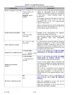
COMP RESTART OFFSET
0.2 - 1.0°C in 0.1 deg
increments
In Continuous Run and when difference between
ambient and setpoint is < 105°C, use the COMP
RESTART OFFSET configuration value for the
switch point to turn cool on (instead of 0.25°C). If
the ambient and setpoint are more than 105°C then
the switch point remains 0.25°C
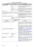
NUMBER OF COMM MODULES
0
–
Not Installed
1 – 1 Optional Comm
Module Installed
If set to 1, this enables alarm
FROM MICRO TO OPTIONAL COMM MODULE
NUMBER OF REMOTE
PANELS
0 – Not Installed
1 – 1 Remote Panel
Installed
If set to 1, this enables alarm
, CAN
Communication failure with Remote Panel.
If set to 0 and a remote panel is connected, the
remote panel will display a message indicating that
the configuration must be changed and will not
operate until then.
NOTE: If set to 1, and number of comm modules is
set to 0, the number of comm modules is
automatically increased to 1 on the main micro. A
remote panel will not be operable without a comm
module.
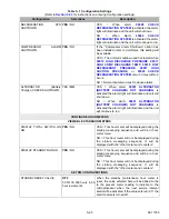
SETPOINT CHANGE ALARM
ON
OFF
This configuration is used to enable/disable No
Setpoint Change Alarm,
When this configuration is set to ON, the No
Setpoint Change Alarm is enabled.
When this configuration is set to OFF, the No
Setpoint Change Alarm is disabled.
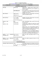
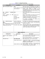
Table 5–1 Configuration Settings
(Refer to
Section 5.2.3
for instructions on entering Configuration settings)
Configuration
Selections
Description
Summary of Contents for VECTOR 8100
Page 2: ......
Page 4: ......
Page 12: ...62 11785 viii ...
Page 16: ...62 11640 12 ...
Page 18: ...62 11785 ...
Page 24: ...62 11785 1 6 1 3 SAFETY DECALS ...
Page 25: ...1 7 62 11785 ...
Page 26: ...62 11785 1 8 ...
Page 27: ...1 9 62 11785 ...
Page 28: ...62 11785 1 10 ...
Page 30: ...62 11785 ...
Page 50: ...62 11785 ...
Page 82: ...62 11785 ...
Page 96: ...62 11785 4 14 ...
Page 98: ...62 11785 ...
Page 129: ...5 31 62 11785 ...
Page 130: ...62 11785 5 32 ...
Page 134: ...62 11785 6 4 ...
Page 138: ...62 11785 ...
Page 230: ...62 11785 ...
Page 271: ...8 41 62 11785 ...
Page 272: ...62 11785 8 42 ...
Page 274: ...62 11785 ...
Page 286: ......
Page 287: ......
Page 288: ...62 11785 10 8 ...
Page 292: ......
Page 293: ......


