62-11785
7–4
00014
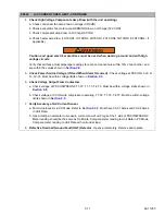
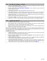
HIGH A/C AMPS
• ACTIVATION: AC Current Sensor 1, 2, or 3 is greater than 28.5A for 3 seconds.
• UNIT CONTROL: Refrigeration system shutdown and alarm with PSCON still energized.
• RESET CONDITION: Auto reset after 14 minutes if AC Current Sensor 1, 2, and 3 reading is less than 27
amps or alarm may be manually reset via keypad or by turning unit off then back on.
NOTE: Follow the steps below until a problem is found. Once a repair or correction has been made, the active
alarm should clear itself (refer to reset condition above). Operate the unit through the appropriate modes to see
if any active alarm occurs. Continue with the steps below as necessary.
CORRECTIVE ACTIONS:
1. Perform Pretrip Check -
Clear Active Alarm list, then run Pretrip & check for any new alarms. Any active
alarms must be corrected and cleared before proceeding.
2. Check Current Draw
a. Use a clamp around A/C ammeter to check amps at power wires. Must be 1.0 Amp of reading in Unit
Data.
b. Check A/C amps with compressor running. Must be greater than 5 Amps.
c. Compare A/C Amp readings between L1-L2-L3. Maximum allowable difference is 10 Amps.
3. Check Wiring
a. Inspect wiring from CT to 1CCB. Check related Splice Points. (See wiring schematic
)
b. Verify there is no physical damage to harness, no damage, moisture, or corrosion in connectors.
00015
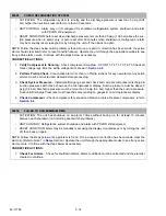
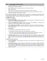
BATTERY VOLTAGE TOO HIGH
• ACTIVATION: Battery voltage at the main microprocessor is greater than 17 VDC.
• UNIT CONTROL: Refrigeration system shutdown and alarm with PSCON still energized.
• RESET CONDITION: Auto reset after 15 minutes when the voltage at the main microprocessor is
between 11 and 14 VDC, or alarm may be manually reset using the display mounted keys or by turning
the unit off, then back on again.
NOTE: Follow the steps below until a problem is found. Once a repair or correction has been made, the active
alarm should clear itself (refer to reset condition above). Operate the unit through the appropriate modes to see
if any active alarm occurs. Continue with the steps below as necessary.
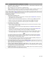
CORRECTIVE ACTIONS:
1.
Check Battery
Voltage
a. Test voltage at battery with unit off. Must be between 11-16 VDC.
b. Test voltage at battery with unit running. Must be between 12-16 VDC.
NOTE
Voltage with unit running should always be higher than voltage with unit off due to battery charging.
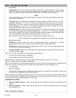
2.
Check Battery Charger
Voltage
a. Test voltage at PCM-T3 with unit off. Must be between 11-16 VDC.
b. Test voltage at PCM-T3 with unit running. Must be between 12-16 VDC.
3.
Check Voltage At Main
Microprocessor
a. Check voltage reading at 3MM-23 & 3MM-34. Must be between 11-16 VDC.
b. Check Unit Data voltage reading. Must be within 0.5 VDC of reading obtained at 3MM-23 & 3MM-
34. If voltages are out with unit running, check Battery Charger. Refer to
.
Summary of Contents for VECTOR 8100
Page 2: ......
Page 4: ......
Page 12: ...62 11785 viii ...
Page 16: ...62 11640 12 ...
Page 18: ...62 11785 ...
Page 24: ...62 11785 1 6 1 3 SAFETY DECALS ...
Page 25: ...1 7 62 11785 ...
Page 26: ...62 11785 1 8 ...
Page 27: ...1 9 62 11785 ...
Page 28: ...62 11785 1 10 ...
Page 30: ...62 11785 ...
Page 50: ...62 11785 ...
Page 82: ...62 11785 ...
Page 96: ...62 11785 4 14 ...
Page 98: ...62 11785 ...
Page 129: ...5 31 62 11785 ...
Page 130: ...62 11785 5 32 ...
Page 134: ...62 11785 6 4 ...
Page 138: ...62 11785 ...
Page 230: ...62 11785 ...
Page 271: ...8 41 62 11785 ...
Page 272: ...62 11785 8 42 ...
Page 274: ...62 11785 ...
Page 286: ......
Page 287: ......
Page 288: ...62 11785 10 8 ...
Page 292: ......
Page 293: ......

