7–7
62-11785
00018
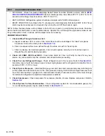
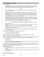
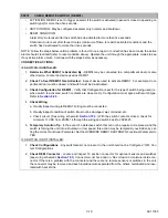
LOW REFRIGERANT PRESSURE
• ACTIVATION: Suction Pressure has been less than -6.3 psig (-0.43 bar) for the Low Suction Pressure
Configuration time or 10 seconds (whichever is less).
• UNIT CONTROL: Alarm only or (if configured for shutdown) refrigeration system shutdown and alarm
with PSCON still energized.
• RESET CONDITION: Auto Reset when suction pressure rises above 0.0 (bar or psig). Alarm may be
manually reset via keypad or by turning the unit OFF, then ON again.
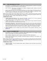
NOTE: Follow the steps below until a problem is found. Once a repair or correction has been made, the active
alarm should clear itself (refer to reset condition above). Operate the unit through the appropriate modes to see
if any active alarm occurs. Continue with the steps below as necessary.
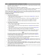
CORRECTIVE ACTIONS:
1.
Visually Inspect
Unit
- Visually inspect unit for damage to liquid line causing restriction or signs of tem-
perature drop at the filter drier. All tubing from the receiver to the evaporator section must be in good con-
dition. Verify that there is no temperature drop at the drier or anywhere on the liquid line.
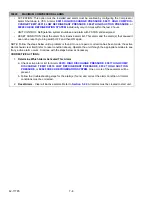
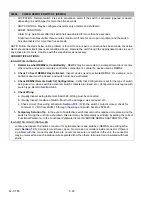
2.
Perform Pretrip
Check
- Clear Active Alarm list, then run Pretrip & check for alarms. Any active alarms
must be corrected and cleared before proceeding.
3.
Check For Low Refrigerant
Charge
- Check refrigerant level in the receiver. Refer to
.
Generally, level should be between upper & lower sight glasses with a refrigerated compartment tem-
perature of 35°F (1.0°C) or lower.
4.
Manually Defrost
Unit
- Defrost unit and terminate automatically. Typical defrost cycle time is 5-20 min-
utes. Suction pressure should rise gradually during cycle.
5.
Check Evaporator
Section
- Check evaporator section, return air bulkhead, air chute, and evaporator
coil for cleanliness and airflow. Refer to
.
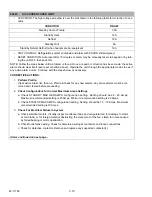
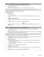
6.
Check System
Pressures
- Install manifold gauge set and check and compare compressor discharge &
suction pressures with those shown on the microprocessor. Suction pressure must be above 0.0 (psig or
bar) Suction & Discharge Pressures must have the same reading on gauges & on microprocessor dis-
play.
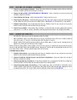
7. Check Transducer Wiring. Refer to
a. Inspect transducer & connector pins & terminals. (See wiring schematic
.) Verify that
there is no physical damage to sensor, and the pins in plug are not damaged or corroded.
b. Check for voltage at the transducer plug between pins A (+) and B (ground). Voltage should be
approximately 12 VDC.
c. Reconnect the transducer plug. Check for voltage between 1MP-29 and ground. Voltage should be
greater than 0.24 VDC and less than 5 VDC.
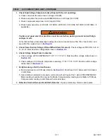
8.
Check Compressor Suction Modulation Valve
(CSMV) -
.
9.
Check Expansion Valve
(EVXV) -
.
Summary of Contents for VECTOR 8100
Page 2: ......
Page 4: ......
Page 12: ...62 11785 viii ...
Page 16: ...62 11640 12 ...
Page 18: ...62 11785 ...
Page 24: ...62 11785 1 6 1 3 SAFETY DECALS ...
Page 25: ...1 7 62 11785 ...
Page 26: ...62 11785 1 8 ...
Page 27: ...1 9 62 11785 ...
Page 28: ...62 11785 1 10 ...
Page 30: ...62 11785 ...
Page 50: ...62 11785 ...
Page 82: ...62 11785 ...
Page 96: ...62 11785 4 14 ...
Page 98: ...62 11785 ...
Page 129: ...5 31 62 11785 ...
Page 130: ...62 11785 5 32 ...
Page 134: ...62 11785 6 4 ...
Page 138: ...62 11785 ...
Page 230: ...62 11785 ...
Page 271: ...8 41 62 11785 ...
Page 272: ...62 11785 8 42 ...
Page 274: ...62 11785 ...
Page 286: ......
Page 287: ......
Page 288: ...62 11785 10 8 ...
Page 292: ......
Page 293: ......

