62-11785
8–22
8.7.8
Expansion Valves, EVXV & ECXV
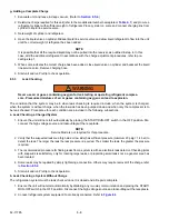
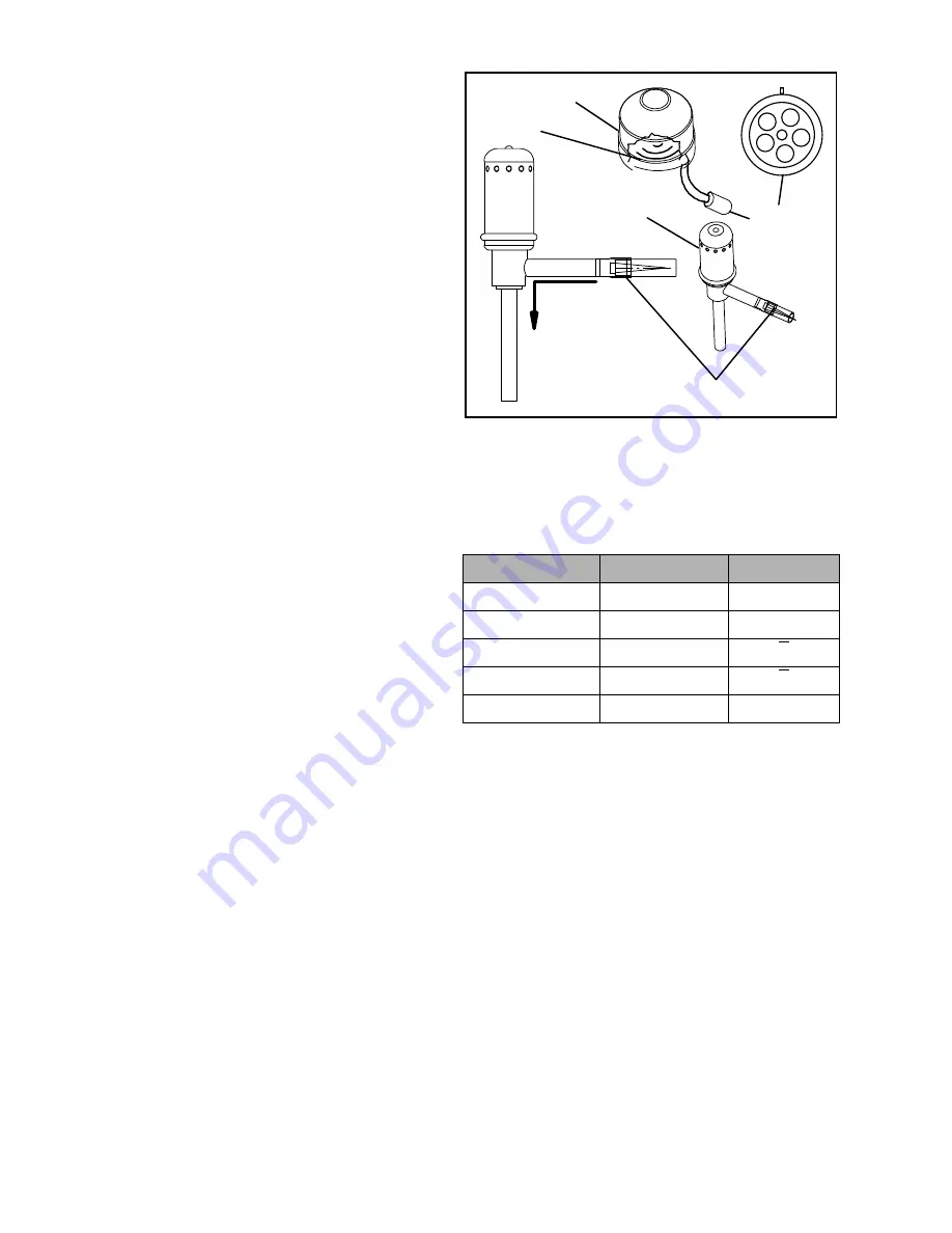
The electronic expansion valves (EVXV = evaporator
expansion valve & ECXV = economizer expansion
valve see
) are automatic devices which
maintain constant superheat of the refrigerant gas
leaving the evaporator/economizer regardless of
suction pressure. The valve functions are: (a)
automatic response of refrigerant flow to match the
evaporator load and (b) prevention of liquid refrigerant
return to the compressor. Unless a valve is defective, it
seldom requires any maintenance.
NOTE
As a preliminary valve check, ensure the coil
is snapped down fully, and the internal coil
retention tab is properly seated in one of the
valve body dimples. Also, check for a tem-
perature drop at the valve inlet strainer loca-
tion, indicating the strainer is restricted or
plugged.
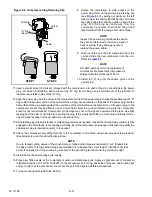
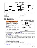
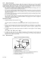
Figure 8.12 Evaporator Expansion Valve
a.Diagnostics - Microprocessor or Wiring
At startup, the APX Control System moves the EVXV and ECXV to known positions. During this time (about 6 sec-
onds after the PER is energized) the voltage sent to the valves can be measured.
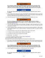
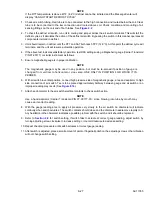
1. Disconnect the 2SVM connector and locate the
wires on the harness side labeled:
EXVA, EXVB, EXVC, EXVD and EXVE
OR
ECVA, ECVB, ECVC, ECVD and ECVE
These will correlate to the connector pins
labeled A, B, C, D and E. Refer to
.
NOTE
The stepper test harness,
, (Carrier Transicold P/N 07-00515) (can also be used to test
the EVXV. If the test harness is used, voltages will be different when measured direct or in-line. The
stepper test harness cannot be used to test the ECXV.
2. Set the voltmeter to the ACV scale. Place the START/RUN
−
OFF switch in the OFF position and disconnect
the starter motor wire at the weather tight connector. Place the START/RUN
−
OFF switch back in the
START/RUN position.
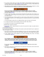
3. Perform the following test on the wiring coming from the SVM: Place the positive (+) voltmeter lead on pin E,
the negative (-) voltmeter lead on pin A and observe the meter for several seconds. The voltage reading will
be approximately 5 to 9 VAC depending on valve position.
4. Leave the positive (+) voltmeter lead on pin E and repeat for pins B, C and D. This procedure may have to
be repeated several times to ensure consistent readings due to the 6 second “home” time.
5. To test the ECXV, start the unit and measure the voltage between pins E & A and then between E & B, E &
C and E & D. A voltage should be read by the digital voltmeter for each pair of wires. If voltage is measured
on all of the wire pairs there is a good signal.
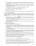
6. If there is no voltage reading, or if the voltage never rises to the 5 to 9 VAC level, it indicates a problem in the
wiring or the SVM. Place the START/RUN
−
OFF switch in the OFF position and reconnect the starter wire.
Test all wiring from the EVXV/ECXV connector to the SVM and verify good continuity, and check the APX
Control System for proper model number configuration before replacing the SVM.
FLOW
DIRECTION
Coil
Boot
Coil
Electronic
Expansion
Valve
Strainer
Five
Pin
Connector
A B
C
D
E
Table 8–2 Expansion Valve Connections
Connector Pin
Wire Color
Winding
A
ORANGE
A
B
RED
B
C
YELLOW
A
D
BLACK
B
E
GREY
COM (+12V)
Summary of Contents for VECTOR 8100
Page 2: ......
Page 4: ......
Page 12: ...62 11785 viii ...
Page 16: ...62 11640 12 ...
Page 18: ...62 11785 ...
Page 24: ...62 11785 1 6 1 3 SAFETY DECALS ...
Page 25: ...1 7 62 11785 ...
Page 26: ...62 11785 1 8 ...
Page 27: ...1 9 62 11785 ...
Page 28: ...62 11785 1 10 ...
Page 30: ...62 11785 ...
Page 50: ...62 11785 ...
Page 82: ...62 11785 ...
Page 96: ...62 11785 4 14 ...
Page 98: ...62 11785 ...
Page 129: ...5 31 62 11785 ...
Page 130: ...62 11785 5 32 ...
Page 134: ...62 11785 6 4 ...
Page 138: ...62 11785 ...
Page 230: ...62 11785 ...
Page 271: ...8 41 62 11785 ...
Page 272: ...62 11785 8 42 ...
Page 274: ...62 11785 ...
Page 286: ......
Page 287: ......
Page 288: ...62 11785 10 8 ...
Page 292: ......
Page 293: ......

