62-11785
8–26
8.7.11
Pressure Transducers
The compressor discharge pressure transducer (CDP) has a range of 0 to 500 psig (0 to 34.0 bar) while the
compressor suction pressure transducer (CSP), evaporator outlet pressure transducer (EVOP), and economizer
pressure transducer (ECOP) have a range of -14.7 to 100 psig (-1 to 6.8 bar). When comparing the transducer
reading in Unit Data to the reading on a manifold gauge, keep in mind the following:
• The compressor discharge pressure reading in Unit Data will never read less than 0 bar/psig, even if it is
exposed to a vacuum (such as when evacuating the system).
• If the compressor discharge pressure transducer has lost power or the signal is not returning to the module
the reading in Unit Data will default to 305 to 315 psig (20.75 to 21.43 bar). Comparisons in this pressure
range are not conclusive.
• The compressor suction pressure and evaporator pressure transducers will never read higher than 100 psig,
even if the actual pressure is higher.
• If the compressor suction pressure or evaporator pressure transducer has lost power or the signal is not
returning to the module the reading in Unit Data will default to 55 to 60 psig (3.74 to 4.08 bar). Comparisons
in this pressure range are not conclusive.
Test Transducer Wiring:
1. Verify that the wiring to the transducer is correct.
NOTE
The CDP connector is identified with a red tape band while the CSP connector is identified with a blue
band.
2. If required, power the transducer circuit by placing the unit in PC Mode, refer to Section 5.3.2. Check Voltage to
transducer connector. Voltage reading between connector position 2 (positive) and position 1 (negative) should
be 5.0 VDC.
3. To check the signal wiring, check continuity between the transducer connector position 3 and the following
connector:
CDP = 2MM-10, CSP = 2MM-9, EVOP = 2MM-17
4. If voltage and signal wire are good, replace the transducer. The transducer may be removed by
disconnecting the connector and quickly backing it off the Schrader valve fitting. Torque replacement
transducer 13 to 15 ft/lb (17.6 to 20.3 Nm).
8.7.12
Defrost Air Switch
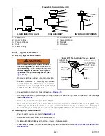
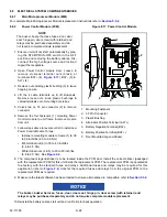
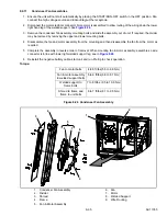
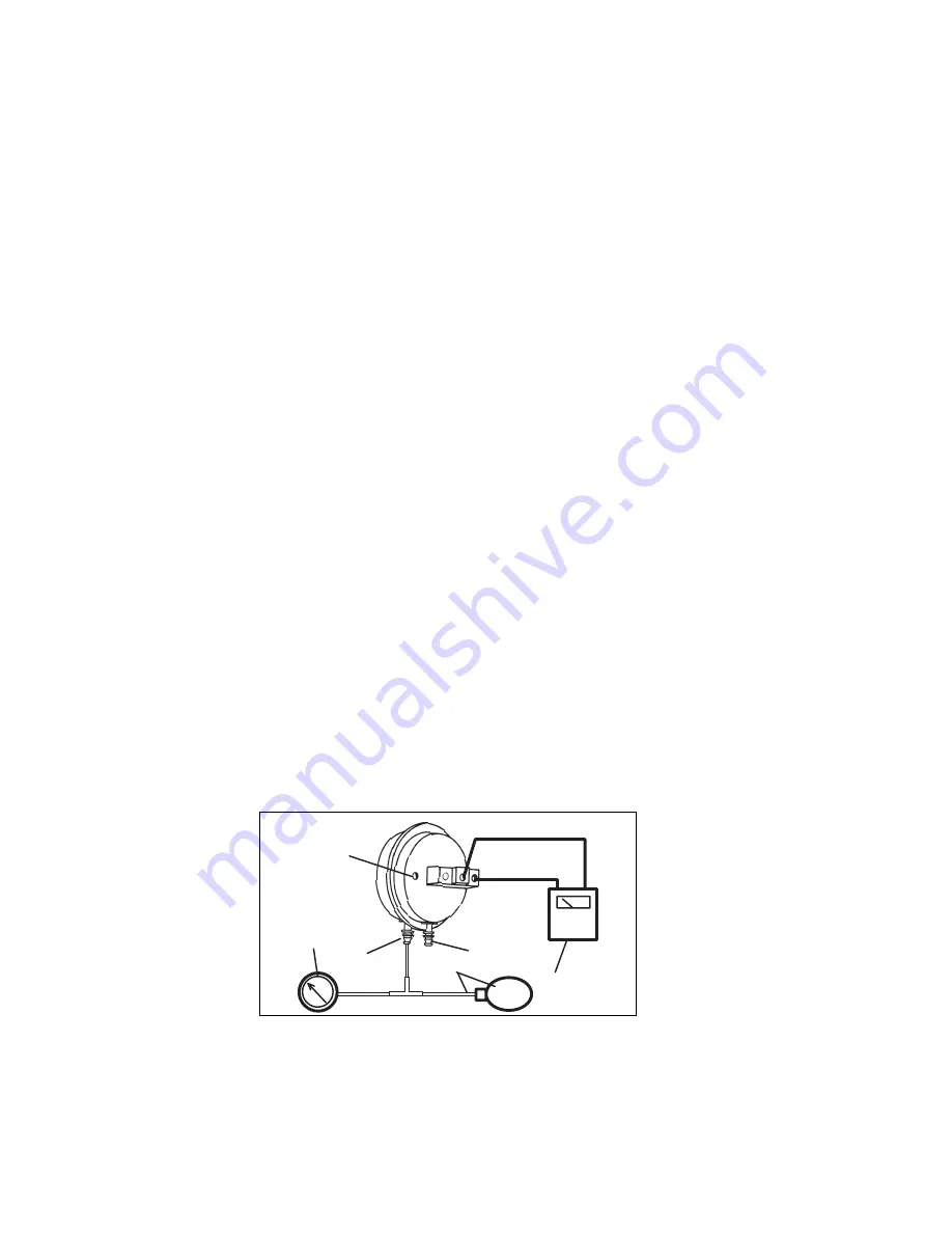
Figure 8.16 Defrost Air Switch Test Setup
1. Ohmmeter or Continuity Device
2. Adjustment Screw (0.050” socket head size)
3. Low Side Connection
4. Pressure Line or Aspirator Bulb (Carrier Transicold P/N 07-00177-01)
5. Magnehelic Gauge (Carrier Transicold P/N 07-00177-00)
6. High Side Connection
- - - - -
Summary of Contents for VECTOR 8100
Page 2: ......
Page 4: ......
Page 12: ...62 11785 viii ...
Page 16: ...62 11640 12 ...
Page 18: ...62 11785 ...
Page 24: ...62 11785 1 6 1 3 SAFETY DECALS ...
Page 25: ...1 7 62 11785 ...
Page 26: ...62 11785 1 8 ...
Page 27: ...1 9 62 11785 ...
Page 28: ...62 11785 1 10 ...
Page 30: ...62 11785 ...
Page 50: ...62 11785 ...
Page 82: ...62 11785 ...
Page 96: ...62 11785 4 14 ...
Page 98: ...62 11785 ...
Page 129: ...5 31 62 11785 ...
Page 130: ...62 11785 5 32 ...
Page 134: ...62 11785 6 4 ...
Page 138: ...62 11785 ...
Page 230: ...62 11785 ...
Page 271: ...8 41 62 11785 ...
Page 272: ...62 11785 8 42 ...
Page 274: ...62 11785 ...
Page 286: ......
Page 287: ......
Page 288: ...62 11785 10 8 ...
Page 292: ......
Page 293: ......


