8–27
62-11785
NOTE
If the DTT temperature is above 40°F (4.4°C) defrost cannot be initiated and the MessageCenter will
display “CANNOT START DEFROST CYCLE”.
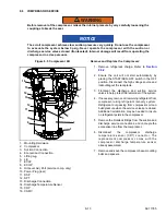
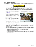
1. Check air switch tubing. Red tube is to be connected to the high connection and routed below the coil. Clear
tube is to be connected to the low connection and routed above coil. Check condition and mounting of air
sensing fittings on the coil end of both tubes. See
.
2. To check the defrost air switch, run unit in cooling and jumper across the air switch terminals. This will start the
defrost cycle as it simulates the action of the defrost air switch. Bypassing the switch in this manner operates all
components involved in defrost.
3. Unit should remain in defrost until the DTT and SAT both reach 55°F (12.8°C). At this point the defrost cycle will
terminate, and the unit will resume automatic operation.
4. If the above test indicates satisfactory operation, test DAS settings using a Magnehelic gauge (Carrier Transicold
P/N 07-00177) or similar instrument as follows.
5. Ensure magnehelic gauge is in proper calibration.
NOTE
The magnehelic gauge may be used in any position, but must be re-zeroed if position of gauge is
changed from vertical to horizontal or vice versa. USE ONLY IN POSITION FOR WHICH IT IS
ZEROED.
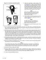
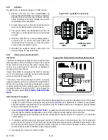
6. With air switch in vertical position, connect high pressure side of magnehelic gauge, a tee and aspirator to high
side connection of air switch. Tee is to be placed approximately half-way between gauge and air switch or an
improper reading may result. (See
7. Attach an ohmmeter to the air switch electrical contacts to check switch action.
NOTE
Use a hand aspirator (Carrier Transicold P/N 07-00177-01), since blowing into tube by mouth may
cause an incorrect reading.
8. With the gauge reading at zero, apply air pressure very slowly to the air switch. An ohmmeter will indicate
continuity when switch actuates. The switch contacts should close and the ohmmeter needle move rapidly to 0.
Any hesitation in the ohmmeter indicates a possible problem with the switch, and it should be replaced.
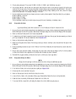
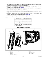
9. Refer to
for switch setting. If switch fails to actuate at correct gauge reading, adjust switch by
turning adjusting screw clockwise to increase setting or counterclockwise to decrease setting.
10. Repeat checkout procedure until switch actuates at correct gauge reading.
11. After switch is adjusted, place a small amount of paint or fingernail polish on the adjusting screw so that vibration
will not change switch setting.
Summary of Contents for VECTOR 8100
Page 2: ......
Page 4: ......
Page 12: ...62 11785 viii ...
Page 16: ...62 11640 12 ...
Page 18: ...62 11785 ...
Page 24: ...62 11785 1 6 1 3 SAFETY DECALS ...
Page 25: ...1 7 62 11785 ...
Page 26: ...62 11785 1 8 ...
Page 27: ...1 9 62 11785 ...
Page 28: ...62 11785 1 10 ...
Page 30: ...62 11785 ...
Page 50: ...62 11785 ...
Page 82: ...62 11785 ...
Page 96: ...62 11785 4 14 ...
Page 98: ...62 11785 ...
Page 129: ...5 31 62 11785 ...
Page 130: ...62 11785 5 32 ...
Page 134: ...62 11785 6 4 ...
Page 138: ...62 11785 ...
Page 230: ...62 11785 ...
Page 271: ...8 41 62 11785 ...
Page 272: ...62 11785 8 42 ...
Page 274: ...62 11785 ...
Page 286: ......
Page 287: ......
Page 288: ...62 11785 10 8 ...
Page 292: ......
Page 293: ......

