62-11785
7–88
25102
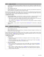
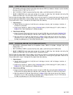
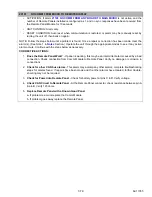
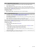
CHECK INPUT VOLTAGE STP1
• ACTIVATION: The stepper input voltage is reported out of valid range (9V to 17V) by stepper board 1 for
3 seconds as timed at stepper board.
• UNIT CONTROL: Alarm only. Steppers on board with problem disabled (Powered OFF) until good power
reported from Stepper Board at which point they are re-enabled.
• RESET CONDITION: 10 seconds of good voltage reported from all steppers.
NOTE: Follow the steps below until a problem is found. Once a repair or correction has been made, clear the
alarm(s). (See Note 1 in
Section.) Operate the unit through the appropriate modes to see if any active
alarm occurs. Continue with the steps below as necessary.
CORRECTIVE ACTIONS:
1.
Check voltages
- Check and verify input voltage at SVM1.
2.
Check Fuse F3
a. Visually check fuse. Verify correct fuse, and check fuse holder for damage, see
Replace fuse as required. Clear alarms, restart and check for repeat alarm(s).
b. Check voltage through the fuse. If fuse is blown, replace it.
c. Check wiring from PCM34 - SP-18 - 2SVM22. Verify there is no physical damage to harness, and
no damage, moisture, or corrosion in connectors.
3.
Disconnect Stepper Valve(s), if alarm goes away:
Check operation of suspected valve. Refer to
25200
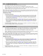
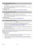
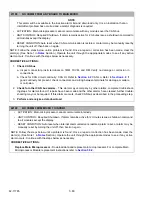
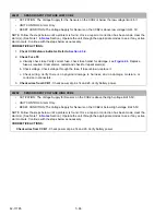
NO COMM FROM MICRO TO STP2
• ACTIVATION: Alarm
21100 NO COMM FROM ANY BOARD TO MAIN MICRO
is not active and no sync
responses have been received from the Stepper 2 Module for 10 seconds.
• UNIT CONTROL: Required Shutdown. If alarm remains active for 2 minutes issue a shutdown command
to all modules except the display.
• RESET CONDITION: Sync response received from the Stepper 2 Module in the past 10 seconds, alarm
reset or alarm may be manually reset by turning the unit off, then back on again.
NOTE: Follow the steps below until a problem is found. Once a repair or correction has been made, clear the
alarm(s). (See Note 1 in
Section.) Operate the unit through the appropriate modes to see if any active
alarm occurs. Continue with the steps below as necessary.
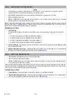
CORRECTIVE ACTIONS:
Check for
25100 NO COMM FROM MICRO TO STP1
- If AL25100 is not present, it indicates the SVM
Board is bad. Replace the SVM Board.
Summary of Contents for VECTOR 8100
Page 2: ......
Page 4: ......
Page 12: ...62 11785 viii ...
Page 16: ...62 11640 12 ...
Page 18: ...62 11785 ...
Page 24: ...62 11785 1 6 1 3 SAFETY DECALS ...
Page 25: ...1 7 62 11785 ...
Page 26: ...62 11785 1 8 ...
Page 27: ...1 9 62 11785 ...
Page 28: ...62 11785 1 10 ...
Page 30: ...62 11785 ...
Page 50: ...62 11785 ...
Page 82: ...62 11785 ...
Page 96: ...62 11785 4 14 ...
Page 98: ...62 11785 ...
Page 129: ...5 31 62 11785 ...
Page 130: ...62 11785 5 32 ...
Page 134: ...62 11785 6 4 ...
Page 138: ...62 11785 ...
Page 230: ...62 11785 ...
Page 271: ...8 41 62 11785 ...
Page 272: ...62 11785 8 42 ...
Page 274: ...62 11785 ...
Page 286: ......
Page 287: ......
Page 288: ...62 11785 10 8 ...
Page 292: ......
Page 293: ......


