62-11640
5–26
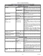
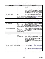
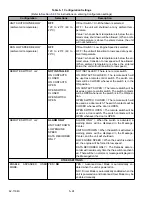
NO AC POWER
ALARM & SHUT-
DOWN
SWITCH TO ENGINE
ALARM & SHUTDOWN = If standby power is lost
unit is to shut down.
SWITCH TO ENGINE = If standby power is lost die-
sel engine will be started.
STANDBY STARTUP DELAY
OFF
5 Seconds
10 Seconds
15 Seconds
20 Seconds
RANDOM
Indicates to the microprocessor the delay for this unit
when starting in standby.
This setting is used when multiple units are on the
same line to stagger the occurrence of high inrush
current in situations such as restart after a power
loss.
If RANDOM is chosen a random time between 0 and
120 seconds will be used. “UNIT WILL START IN XX
SECONDS” will display during the count down period.
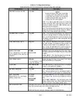
SUCTION PRESSURE
30 PSIG (2.0 BAR)
0 - 50 psig (0 to 3.4 bar)
[in 1 psig (0.1 bar) incre-
ments]
Pressure to maintain if discharge pressure transduc-
er is opened or shorted.
STANDBY MAX GEN AMPS
22A
10 to 35 in 0.5A incre-
ments
Indicates to the microprocessor the maximum allow-
able amperage in Electric operation.
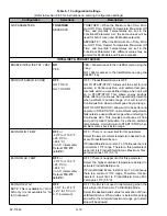
USE FACTORY DEFAULT SETTING ONLY. DO
NOT OPERATE UNIT WITH DIFFERENT SETTING.
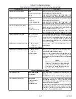
SUPPLY AIR LIMIT FOR S/S
-21.6°F to -2.7°F
(-12°C to -1.5°C) in
0.5°F or °C increments.
DEFAULT: -21.6
°
F (-
12
°
C)
Value to be used to calculate the lowest allowable
supply air temperature, when in Start-Stop Opera-
tion, in accordance with the formula “Se this
value = coldest allowable supply air temperature“.
For example:
Fahrenheit: if the setpoint is 35°F and the Configura-
tion value is set at -10°F the calculation is 35 + (-10)
= 25°F lowest allowed supply air temperature.
Celsius: if the setpoint is 2°C and the Configuration
value is set at -6°C the calculation is 2 + (-6) = -4°C
lowest allowed supply air temperature.
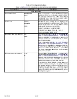
SUPPLY AIR LIMIT FOR CONT -21.6°F to 1.8°F
(-12°C to -1°C)
(in 0.5°F or °C incre-
ments)
DEFAULT: -4.5
°
F
(-2.5
°
C)
Value to be used to calculate the lowest allowable
supply air temperature, when in Continuous Opera-
tion, in accordance with the formula “Se this
value = coldest allowable supply air temperature“.
For example:
Fahrenheit: if the setpoint is 35°F and the Configura-
tion value is set at -10°F the calculation is 35 + (-10)
= 25°F lowest allowed supply air temperature.
Celsius: if the setpoint is 2°C and the Configuration
value is set at -6°C the calculation is 2 + (-6) = -4°C
lowest allowed supply air temperature.
HIGH SPEED PULLDOWN
ON /
OFF
When active, this logic indicates if temperature limits
regulating the exit of pulldown mode are modified or
not.
ON = Unit will continue in High Speed until it reaches
setpoint.
Table 5–1 Configuration Settings
(Refer to
Section 5.2.3
for instructions on entering Configuration settings)
Configuration
Selections
Description
Summary of Contents for Vector 8500
Page 23: ...62 11640 1 6 1 3 SAFETY DECALS ...
Page 24: ...1 7 62 11640 62 03958 ...
Page 25: ...62 11640 1 8 ...
Page 26: ...1 9 62 11640 ...
Page 27: ...62 11640 1 10 ...
Page 125: ...62 11640 SECTION 6 MESSAGECENTER PARAGRAPH NUMBER Page 6 1 MESSAGECENTER MESSAGES 6 1 ...
Page 321: ......
Page 322: ......


