62-11640
7–18
00027
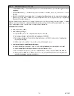
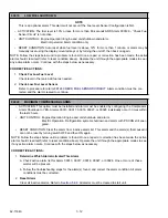
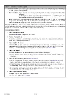
HIGH SUCTION PRESSURE
• ACTIVATION: The refrigeration system is running and the suction pressure has been greater than 98 psig
(6.7 bar) for more than 10 minutes.
• UNIT CONTROL: Engine Operation: Alarm only or (if configured for shutdown) engine and unit shutdown
and alarm.
Electric Operation: Alarm only or (if configured for shutdown) refrigeration system shut-
down and alarm with PSCON still energized.
• RESET CONDITION: Auto reset when suction pressure is less than 75 psig (5.1 bar) for 5 minutes and
configured for Alarm Only, or Auto Reset after 15 minutes if configured as a Shutdown Alarm or, alarm
may be manually reset via keypad or by turning the unit off, then back on again.
NOTE: Follow the steps below until a problem is found. Once a repair or correction has been made, the active
alarm should clear itself (refer to reset condition above). Operate the unit through the appropriate modes to see
if any active alarm occurs. Continue with the steps below as necessary.
CORRECTIVE ACTIONS:
1.
Check Refrigerant
Charge
Refer to
2.
Perform Pretrip
Check
Clear Active Alarm list, then run Pretrip & check for any new alarms. Any active alarms must be cor-
rected and cleared before proceeding.
3.
Check System
Pressures
Install manifold gauge set and check and compare compressor discharge & suction pressures with
those shown in Unit Data. Suction pressure must be above 3 psig (0.2 bar) and should be in the nor-
mal range for ambient & refrigerated compartment conditions. Refer to
.
4.
Check
Compressor
a. Check compressor for excessive vibration or noise. Replace compressor
b. Cover condenser and build-up discharge pressure. Must be able to raise pressure to 400 psig
(27.2 bar).
5.
Check Transducer Wiring. Refer to
a. Inspect transducer & connector pins & terminals. (See wiring schematic
.) Verify
there is no physical damage to sensor. Verify there is no damaged or corroded pins in plug.
b. Check for voltage at the transducer plug between pins A (+) and B (ground). Voltage should be
approximately12VDC. If OK, go to next step. If not, continue with this step.
c. Reconnect the transducer plug. Check for voltage between 1MP
−
29 and ground. Voltage should
be greater than 0.24 VDC and less than 5 VDC.
6.
Check Expansion Valve
(EVXV)
a. Visually inspect valve. Check coil is seated properly.
b. Check valve. Refer to
Summary of Contents for Vector 8500
Page 23: ...62 11640 1 6 1 3 SAFETY DECALS ...
Page 24: ...1 7 62 11640 62 03958 ...
Page 25: ...62 11640 1 8 ...
Page 26: ...1 9 62 11640 ...
Page 27: ...62 11640 1 10 ...
Page 125: ...62 11640 SECTION 6 MESSAGECENTER PARAGRAPH NUMBER Page 6 1 MESSAGECENTER MESSAGES 6 1 ...
Page 321: ......
Page 322: ......

