62-11640
7–40
00075
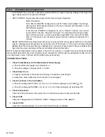
COMP MOTOR OVERLOAD
• ACTIVATION: If alarm 00022, 00027 and/or 00028 was triggered with current below 5.5 amps, this alarm
will also trigger or on restart from alarm 00022, 00027 and/or 00028 trigger on if compressor current does
not rise above 1 amp, and alarm 00013 (High Discharge Pressure) is not active.
• UNIT CONTROL: Engine: Engine and unit shutdown and alarm.
Electric: Refrigeration system shutdown and alarm with PSCON still energized.
NOTE
The compressor motor is fitted with an internal line break that may have caused this alarm. The line
break is an auto reset device. Additional time may be required to reduce winding temperature to the
reset temperature of this device.
• RESET CONDITION: Auto reset after 30 minutes alarm may be manually reset via keypad or by turning
the unit off, then back on again.
NOTE: Follow the steps below until a problem is found. Once a repair or correction has been made, the active
alarm should clear itself (refer to reset condition above). Operate the unit through the appropriate modes to see
if any active alarm occurs. Continue with the steps below as necessary.
CORRECTIVE ACTIONS:
1.
Check For Alarms 00022, 00027 and/or 00028 (Check Download)
00022, 00027 and/or 00028 will always cause this alarm to activate Review steps for triggered
alarms and correct if necessary.
2.
Check Compressor Power Supply
Start unit and check voltage. Normal low speed voltage at contactor should be greater than 360 and
less than 460V. Check current on each phase. Current must be greater than 0 and less than 18
amps. (Compressor is operating.) If voltage is present and current is 0, motor is overheated. Wait for
compressor to cool for 30 minutes and check again. If voltage and current are not present at load
side of contact check compressor contactor operation.
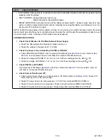
3.
Check Compressor Motor Contactor
Check condition and wiring Repair/replace as required.
4.
Check Airflow Through Radiator / Condenser Coil
a. Inspect condenser / radiator fins. Fins must be straight. 90% or more of the coil surface must be
undamaged. No “dead” air spaces. Coil must be clean (refer to
b. Check condenser airflow. Even airflow through the entire coil. No “dead” spots.
c. Check condenser fan rotation / operation. Fans should operate correctly. Air drawn in through the
grill, and directed into the engine compartment.
5.
Check System For Non-Condensables, Low Charge
Check refrigeration system for noncondensable gas(es). No non-condensable gas(es) may be pres-
6.
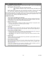
Perform Pretrip, Verify SMV and ECEV Functionality
Clear Active Alarm list, then run Pretrip & check for any new alarms. Any active alarms must be cor-
rected and cleared before proceeding.
7.
Verify Accuracy of AC Current Sensor
a. Put microprocessor in PC Mode. Refer to
page 5
−
8. Must have 0 AC1 Amps and 0
AC2 Amps in Unit Data.
b. Use a clamp on ammeter to measure current draw of all 3 legs of the T side of GENCON. Meter
reading should be the same as Unit Data: Compare meter reading to Unit Data in PC Mode. Com-
pare meter reading to Unit Data with unit under load.
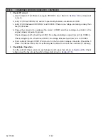
8.
Check Compressor
Check compressor for excessive vibration or noise. Replace compressor. Refer to
Summary of Contents for Vector 8500
Page 23: ...62 11640 1 6 1 3 SAFETY DECALS ...
Page 24: ...1 7 62 11640 62 03958 ...
Page 25: ...62 11640 1 8 ...
Page 26: ...1 9 62 11640 ...
Page 27: ...62 11640 1 10 ...
Page 125: ...62 11640 SECTION 6 MESSAGECENTER PARAGRAPH NUMBER Page 6 1 MESSAGECENTER MESSAGES 6 1 ...
Page 321: ......
Page 322: ......

