7–59
62-11640
P00141
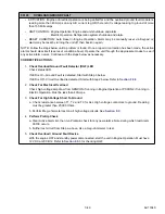
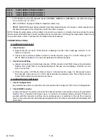
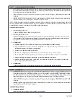
PRETRIP STOPPED BY USER
• ACTIVATION: Pretrip cycle was stopped by user before the Pretrip cycle ended automatically.
• UNIT CONTROL: Engine and Electric Operation: Alarm Only.
• RESET CONDITION: Alarm may be manually reset using the display mounted keys or by turning the unit
off, then back on again.
NOTE: Follow the steps below until a problem is found. Once a repair or correction has been made, clear the
alarm(s). (Refer to Note 1 in
Section, page 7-2.) Operate the unit through the appropriate modes to see if
any active alarm occurs. Continue with the steps below as necessary.
CORRECTIVE ACTIONS:
1.
Check For Any Pretrip Alarms
Scroll the alarm list for any Active Pretrip alarms. Alarm conditions must be corrected and the alarm
cleared to continue.
2.
Rerun Pretrip Check (If Desired)
a. Clear Active Alarm List, then run Pretrip & check for any new alarms. Unit is in Pretrip. Check for
any new alarms.
b. Allow to terminate automatically. Pretrip cycle operates normally.
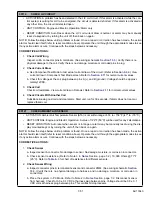
P00151
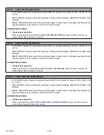
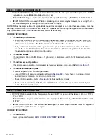
CHECK GLOW CIRCUIT (This applies to the engine preheater = EPH)
• ACTIVATION: The circuit current draw is outside the normal range.
• UNIT CONTROL: Engine and Electric Operation: Pretrip will fail in test 2 and display “PRETRIP FAIL
AND COMPLETED”.
• RESET CONDITION: Auto reset if Pretrip is started again or alarm may be manually reset using the dis-
play mounted keys or by turning the unit off then back on again.
CORRECTIVE ACTIONS:
1.
Check glow plug operation
00040 CHECK ENGINE PREHEAT CIRCUIT
. Alarm condition must be
corrected and the alarm cleared to continue.
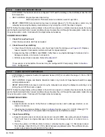
P00152
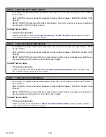
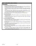
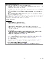
CHECK FUEL SOLENOID CIRCUIT
• ACTIVATION: The circuit current draw is outside the normal range.
• UNIT CONTROL: Engine and Electric Operation: Pretrip will fail in test 2 and display “PRETRIP FAIL
AND COMPLETED”.
• RESET CONDITION: Auto reset if Pretrip is started again or alarm may be manually reset using the dis-
play mounted keys or by turning the unit off then back on again.
NOTE: Follow the steps below until a problem is found. Once a repair or correction has been made, clear the
alarm(s). (Refer to Note 1 in
Section, page 7-2.) Operate the unit through the appropriate modes to see if
any active alarm occurs. Continue with the steps below as necessary.
CORRECTIVE ACTIONS:
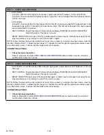
1.
Check ENCU operation
Refer to procedure for alarm
05012 CHECK ENCU POWER CIRCUIT
. Alarm condition must be cor-
rected and the alarm cleared to continue.
Summary of Contents for Vector 8500
Page 23: ...62 11640 1 6 1 3 SAFETY DECALS ...
Page 24: ...1 7 62 11640 62 03958 ...
Page 25: ...62 11640 1 8 ...
Page 26: ...1 9 62 11640 ...
Page 27: ...62 11640 1 10 ...
Page 125: ...62 11640 SECTION 6 MESSAGECENTER PARAGRAPH NUMBER Page 6 1 MESSAGECENTER MESSAGES 6 1 ...
Page 321: ......
Page 322: ......

