background image

62-11640

7–64

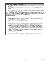
P00174

CHECK LOW SPEED RPM

• ACTIVATION: 

in Test #4: With the CAN calling for low speed, engine speed is NOT between: 1300 and 1400 rpm. 
in Test #6: 15 seconds after the high speed test, engine rpm has not dropped from the high speed test to
1300 to 1400 rpm.

• ACTIVATION 

in Test #6: 15 seconds after the High Speed Pretrip Test #5, engine speed has NOT dropped back to the
low speed range (within 15 seconds) as shown above. Note: This test will be skipped if the engine speed
sensor alarm (A00130) is active. 

• UNIT CONTROL: Engine Operation: Pretrip will fail and display “PRETRIP FAIL AND COMPLETED”. 

Electric Operation: This test is not made. 

• RESET CONDITION: Auto reset if Pretrip is started again or alarm may be manually reset using the dis-

play mounted keys or by turning the unit off then back on again. 

NOTE: Follow the steps below until a problem is found. Once a repair or correction has been made, clear the
alarm(s). (Refer to Note 1 in 

Notes

 Section, page 7-2.) Operate the unit through the appropriate modes to see if

any active alarm occurs. Continue with the steps below as necessary. 

CORRECTIVE ACTIONS:

1.

Check low speed operation


Refer to procedure for alarm 

00037 CHECK LOW SPEED RPM

Alarm condition must be corrected

and the alarm cleared to continue.

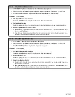
P00175

CHECK HIGH SPEED RPM

• ACTIVATION: In Test #5 with the CAN calling for high speed, engine speed is NOT between: 1750 and

1850 rpm.

• UNIT CONTROL: Engine Operation: Pretrip will fail and display “PRETRIP FAIL AND COMPLETED”. 

Electric Operation: This test is not made. 

• RESET CONDITION: Auto reset if Pretrip is started again, or Alarm may be manually reset using the dis-

play mounted keys or by turning the unit off, then back on again. 

NOTE: Follow the steps below until a problem is found. Once a repair or correction has been made, clear the
alarm(s). (Refer to Note 1 in 

Notes

 Section, page 7-2.) Operate the unit through the appropriate modes to see if

any active alarm occurs. Continue with the steps below as necessary. 

CORRECTIVE ACTIONS:

1.

Check high speed operation

.

Refer to procedure for alarm 

00038 CHECK HIGH SPEED RPM

. Alarm condition must be corrected

and the alarm cleared to continue.

Summary of Contents for Vector 8500

Page 1: ...Trailer Rail Refrigeration EVXV EVAPORATOR EVOT EVOP MM DISTRIBUTOR OPERATION SERVICE MANUAL For The VECTOR 8500 Single Temp Trailer and Rail Refrigeration Units 62 11640 Rev B Change 09 14 ...

Page 2: ...OPERATION SERVICE MANUAL For The VECTOR 8500 Single Temp Trailer and Rail Refrigeration Units Carrier Corporation 2014 Printed in U S A September 2014 ...

Page 3: ...HPS 2 7 d Compressor Discharge Temperature Sensor CDT 2 7 e Compressor Suction Temperature Sensor CST 2 7 2 3 7 Liquid Injection Solenoid Valve LIV 2 7 2 3 8 Condenser Coil 2 7 2 3 9 Economizer Circuit 2 7 2 3 10 Economizer Transducer and Sensor 2 7 a Economizer Outlet Pressure Transducer ECOP 2 7 b Economizer Outlet Temperature Sensor ECOT 2 7 2 3 11 Ambient Air Temperature Sensor AAT 2 7 2 3 12 ...

Page 4: ... 6 3 Remote Temperature Sensor 2 13 2 6 4 Fuel Level Sensor 2 13 2 6 5 Fuel Heater 2 13 2 6 6 Electric Fuel Pump 2 13 2 6 7 Remote Panel 2 13 2 7 ENGINE DATA 2 14 2 8 COMPRESSOR DATA 2 14 2 9 REFRIGERATION SYSTEM DATA 2 15 2 10 ELECTRICAL DATA 2 15 2 11 COMPONENT RESISTANCE CURRENT DRAW 2 16 2 12 SAFETY DEVICES 2 17 2 13 REFRIGERATION CIRCUIT DURING COOLING 2 17 2 13 1 Standard Mode 2 17 2 13 2 Ec...

Page 5: ... 4 5 1 Start Stop Configuration 4 4 4 5 2 Stop Parameters 4 4 1 Unit has run for the selected Minimum Run Time 4 4 2 Engine coolant temperature has warmed 4 4 3 Battery is fully charged Voltage 4 4 4 Battery is fully charged Amperage 4 5 5 Compartment temperature requirement is satisfied 4 5 4 5 3 Re Start Parameters 4 5 1 Engine coolant temperature drops below selected Configuration value 4 5 2 B...

Page 6: ...4 Component Test Mode 5 6 5 2 5 Service Mode 5 7 5 3 USB MEMORY DEVICES 5 7 5 3 1 Data Transfer USB Memory Device 5 7 5 3 2 PC Mode 5 8 5 3 3 Downloading Data Files 5 9 5 3 4 Installing Software 5 10 5 3 5 Transferring Configuration Files 5 11 5 4 TRU TECH TRU VIEW 5 12 5 4 1 TRU Tech 5 12 5 4 2 TRU View 5 12 5 4 3 Connecting Computer and Control System 5 12 5 5 MAIN MICROPROCESSOR REPLACEMENT SET...

Page 7: ...T TEMPERATURE 7 23 00037 CHECK LOW SPEED RPM 7 23 00038 CHECK HIGH SPEED RPM 7 24 00039 CHECK ENGINE RPM 7 25 00040 CHECK ENGINE PREHEAT CIRCUIT 7 26 00041 ENGINE STALLED 7 27 00051 ALTERNATOR BATTERY CHARGER NOT CHARGING 7 29 00053 BOX TEMP OUT OF RANGE 7 30 00054 DEFROST NOT COMPLETE 7 32 00055 CHECK DEFROST AIR SWITCH 7 33 00057 CHECK REMOTE SWITCH 1 REMS1 7 34 00058 CHECK REMOTE SWITCH 2 REMS2...

Page 8: ...AIR SENSOR 7 60 P00154 CHECK SUPPLY AIR SENSOR 7 60 P00155 CHECK COOLANT TEMP SENSOR 7 60 P00157 CHECK BATTERY CURRENT 7 61 P00158 CHECK AMBIENT AIR SENSOR 7 61 P00159 CHECK DEFROST TERM 1 SENSOR 7 62 P00160 CHECK DISCHARGE TEMP SENSOR 7 62 P00161 CHECK SUCTION TEMP SENSOR 7 62 P00162 CHECK AFA SOLENOID CIRCUIT 7 63 P00170 CHECK LIV CIRCUIT 7 63 P00173 CHECK ECONOMIZER 7 63 P00174 CHECK LOW SPEED ...

Page 9: ...012 CHECK ENCU POWER CIRCUIT 7 94 05014 CHECK STARTER SOLENOID CIRCUIT 7 95 05016 CHECK REMOTE AMBER LIGHT 7 95 05017 CHECK ENG PREHEAT ENABLE CIRCUIT 7 96 05018 CHECK POWER ENABLE CONTROL 7 97 05019 CHECK CDCON2 COIL 7 97 05020 CHECK HTR CNTR ONE 7 98 05021 CHECK HTR CNTR TWO 7 99 06000 CONDENSER MOTOR2 OVERHEATED 7 100 06001 CHECK LIGHT BAR 7 102 07000 ECONOMIZER TEMP SENSOR 7 102 07001 ECONOMIZ...

Page 10: ...N SENSOR ABNORMAL 7 119 26109 ACTUATOR ABNORMAL ENCU 7 119 26110 ENGINE SPEED SENSOR ABNORMAL 7 120 27200 NO COMM FROM MICRO TO COMM MODULE 7 120 SERVICE 8 1 8 1 SECTION LAYOUT 8 1 8 2 SCHEDULED MAINTENANCE 8 1 8 3 PRE TRIP INSPECTION 8 2 8 4 EXTERNAL SURFACE SERVICE 8 4 8 4 1 AutoFresh Fresh Air Exchange 8 4 a Cover And Or Cover Gaskets 8 4 b Solenoid 8 4 8 4 2 Grille Insert Removal 8 4 8 4 3 Sur...

Page 11: ...arge 8 17 8 6 3 Leak Checking 8 18 a Leak Checking a Charged System 8 18 b Leak Checking a System Without Charge 8 18 c Leak Checking With Low Side Pumped Down 8 19 d Leak Checking Compressor 8 19 8 6 4 Evacuation and Dehydration 8 20 a Evacuation of the Complete System 8 20 b Evacuation of the Low Side 8 21 c Evacuation of the Compressor 8 21 8 7 COMPRESSOR SERVICE 8 22 8 8 REFRIGERANT SYSTEM COM...

Page 12: ...gohmmeter Test Procedure 8 35 8 9 7 Light Bar 8 36 8 9 8 Overload Ground Fault OGF 8 36 a Operation 8 36 b OGF Checkout Procedure 8 36 8 9 9 Evaporator Heaters 8 37 8 9 10 Evaporator Blower Motor 8 37 8 9 11 Condenser Fan Assemblies 8 38 8 9 12 Battery Charger BTYC 8 39 8 9 13 Generator 8 40 a Preventive Maintenance and Operating Precautions 8 40 b Generator Replacement 8 40 c Generator Removal 8 ...

Page 13: ... Terminate Heating 9 6 9 4 7 Defrost Cycle Malfunction 9 6 9 4 8 Abnormal Pressure Cooling 9 7 9 4 9 Abnormal Noise 9 7 9 4 10 No Evaporator Air Or Flow Or Restricted Air Flow 9 7 9 4 11 Expansion Valve EVXV Malfunction 9 8 9 4 12 Compressor Suction Modulation Valve CSMV Malfunction 9 8 9 4 13 Economizer Valve ECXV Malfunction 9 8 9 4 14 Abnormal Discharge Temperature High 9 8 WIRING 10 1 10 1 HAR...

Page 14: ...ock Settings Non Overlapping 4 11 Figure 4 3 Range Lock Settings Overlapping 4 11 Figure 5 1 Technician Mode 5 1 Figure 5 2 Technician Hour Meters 5 2 Figure 5 3 Inactive Alarms 5 3 Figure 5 4 Setting Configurations 5 4 Figure 5 5 Component Test Mode 5 6 Figure 5 6 PC Mode 5 8 Figure 5 7 Downloading Data Files 5 9 Figure 5 8 Installing Software 5 10 Figure 5 9 Transferring Configuration Files 5 11...

Page 15: ...e 8 30 CCB Location in Control Box 8 34 Figure 8 31 CCB Location in Control Box 8 35 Figure 8 32 Meghommeter Connection to Ground Plate 8 35 Figure 8 33 Light Bar Connections 8 36 Figure 8 34 Overload Ground Fault Connections 8 36 Figure 8 35 Evaporator Blower Assembly 8 38 Figure 8 36 Condenser Fan Assembly 8 39 Figure 8 37 Generator UniDrive Assembly 8 40 Figure 8 38 Exhaust Connection Disassemb...

Page 16: ... Table 3 2 Functional Parameters 3 25 Table 4 1 Engine Preheat Time 4 3 Table 5 1 Configuration Settings 5 16 Table 6 1 MessageCenter Messages 6 1 Table 8 1 Maintenance Schedule 8 2 Table 8 2 Expansion Valve Connections 8 28 Table 8 3 Sensor Resistance 8 45 Table 8 4 Sensor Resistance CDTS 8 46 Table 8 5 Temperature Pressure Chart 8 47 ...

Page 17: ...62 11640 SECTION 1 SAFETY PARAGRAPH NUMBER Page 1 1 SAFETY PRECAUTIONS 1 1 1 2 SPECIFIC WARNING CAUTION AND NOTICE STATEMENTS 1 2 1 3 SAFETY DECALS 1 6 ...

Page 18: ...Improper use of voltmeters jumper wires continuity testers etc could per manently damage the module Automatic Start Stop Your refrigeration unit is equipped with auto start in both Start Stop and Continuous Operation The unit may start at any time the START RUN OFF switch SROS is in the START RUN position A buzzer will sound for 5 seconds before the unit is started When performing any check of the...

Page 19: ...art automatically at any time the START RUN OFF switch SROS is in the START RUN position Also the unit may be fitted with two way communication equipment that will allow starting of the unit from a remote location even though the switch is in the OFF position WARNING Be aware of HIGH VOLTAGE supplied at the power plug or from the generator When performing service or maintenance procedures ensure a...

Page 20: ...plosion WARNING Disconnect batteries before doing any electrical welding on unit or chassis to which unit is attached trailer container rail car metal building etc WARNING Inspect battery cables for signs of wear abrasion or damage at every pre trip inspection and replace if necessary Also check battery cable routing to ensure that clamps are secure and that cables are not pinched or chafing again...

Page 21: ...nal Electric Manufacturer s Association NEMA rules and test equipment manufacturers instructions NOTICE Electronic modules MUST be handled with care to prevent accidental damage or degradation from electrostatic dis charge ESD contamination or abuse Before touching a module touch your body and or conductive tool being used to the frame to discharge ESD safely All electronics should be handled care...

Page 22: ... always be added to a cold engine NOTICE Use only ethylene glycol anti freeze with inhibitors in system as glycol by itself will damage the cooling system Always add pre mixed 50 50 anti freeze and water to radiator engine Never exceed more than a 60 concentration of anti freeze Use a low silicate anti freeze meeting GM specifications GM 6038M for standard life coolant or use Texaco Havoline exten...

Page 23: ...62 11640 1 6 1 3 SAFETY DECALS ...

Page 24: ...1 7 62 11640 62 03958 ...

Page 25: ...62 11640 1 8 ...

Page 26: ...1 9 62 11640 ...

Page 27: ...62 11640 1 10 ...

Page 28: ... 2 8 2 4 1 Evaporator Coil 2 8 2 4 2 Evaporator Expansion Valve EVXV 2 8 2 4 3 Evaporator Switches Transducers and Sensors 2 8 2 5 SYSTEM OPERATING CONTROLS AND COMPONENTS 2 9 2 5 1 Automatic Start Stop 2 9 2 5 2 Special Features 2 9 2 5 3 Component Description and Location 2 9 2 6 OPTIONS 2 12 2 6 1 Light Bar 2 12 2 6 2 Remote Switch es 2 13 2 6 3 Remote Temperature Sensor 2 13 2 6 4 Fuel Level S...

Page 29: ...control modules fuses and associated wiring High voltage contactors fuses and the contactor control boards are located in the control box while contactors for the optional standby electric power are located in the standby box see Figure 2 4 The unit may be equipped with an optional remote light bar which mounts separately on the front outside corner of the refrigerated compartment Temperature cont...

Page 30: ...essor Discharge Service Valve 11 High Pressure Switch HPS Located in service valve 12 Compressor Discharge Pressure Transducer CDP located in discharge line 13 Compressor Suction Temperature Sensor CST 14 Economizer Outlet Temperature Sensor ECOT 15 Compressor Suction Modulation Valve CSMV 16 Liquid Injection Valve LIV 17 Economizer Expansion Valve ECXV 18 Economizer Outlet Pressure Transducer ECO...

Page 31: ...cle PSR 17 Engine Oil Filter 18 Mechanical Fuel Pump 19 Engine Oil Fill Dipstick 20 Rack Position Sensor RPS 21 Engine Oil Drain 22 Starter SS SSC SM 23 Engine Preheater EPH 24 Engine Coolant Temperature Sensor ENCT Behind Engine Preheater 25 Generator GEN 26 Battery BTY 27 Power Control Module PCM See Figure 2 5 28 Main Microprocessor Module MM 29 Air Cleaner Air Cleaner Service Indicator Mani fo...

Page 32: ...h Tubing Clear 8 High Pressure Defrost Air Switch Tubing Red 9 Defrost Termination Temperature Sensor 1DTT 10 High Pressure Air Switch Fitting 11 Drain Pan Heater HTR1 12 Defrost Heaters HTR1 2 13 Return Air Temperature Sensor 1RAT 14 EVXV Inlet Strainer Location 15 Evaporator Outlet Pressure Transducer EVOP and Evaporator Outlet Temperature Sensor EVOT 16 Evaporator Expansion Valve EVXV Located o...

Page 33: ...or Power 12A 11 Fuse F36 Fan Motor Power 12A 12 Contactor Control Board 2 2CCB 13 AC Current Sensor CT 1 2 3 14 Generator Contactor GENCON 15 Compressor Contactor CCON 16 High Voltage Transformer HVT 17 Ground Plate PE 18 Power Supply Contactor 2 PSCON2 19 Power Supply Contactor PSCON 20 Overload Ground Fault OGF 21 Contactor Control Board 1 1CCB 22 Fuse F35 Battery Charger Power 5A 23 Fuse F34 Ba...

Page 34: ...ne component Fuel supply to the injectors and engine speed is controlled by varying rod position in accordance with the signal from the control system In order to ease the load on the system speed transition high to low and low to high is ramped up or down over a 10 second period The FSA is located on the front of the gear case cover b Engine Speed Sensor ENSSN The ENSSN provides the control syste...

Page 35: ...eaving the receiver Air movement over the con denser subcooler radiator is provided by the con denser fans 2 3 9 Economizer Circuit The economizer circuit consists of a compact brazed plate heat exchanger Figure 2 1 and the economizer expansion valve ECXV Both are located above the compressor In the economized mode the frozen and pull down capacity of the unit is increased by subcooling the liq ui...

Page 36: ...t over the coil is provided by the evaporator fan and motor EVM assembly The electric heaters HTR1 HTR2 are mounted on the inlet side of the coil and in the drain pan Automatic evaporator coil defrosting is initiated by either a defrost air switch DAS which senses the pressure drop across the coil or by the control system defrost timer During defrost the refrigeration system is shut down and the e...

Page 37: ...n DataLink data recorder memory USB communication for downloading data upgrading operational software and Configura tion set up Automatic Engine Starting Functional Parameter locks Alarms are stored in control system memory for future reference ATM style menu system which reduces key strokes Dashboard display screens which display up to 5 data points simultaneously Backlit Carrier Blue silicone ke...

Page 38: ...tions Power 16 Fuse F11 5 amp Light Bar Power 17 Fuse F10 20 amp Main Microprocessor Module Component Actuation Power 18 Fuse F9 5 amp Contactor Control Board Component Actuation Power 19 Fuse F8 5 amp Fuel Level Sensor Power With EES installed F8 10 amp for FLS EES b Main Microprocessor Module The main microprocessor module MM houses the main system microprocessor The module is totally self conta...

Page 39: ... pro vides a reading of each individual AC line current draw amps to the main microprocessor through the CAN bus from 1CCB at terminals 1CCB 12 34 10 31 see schematic diagram Section 10 g High Voltage Transformer HVT The high voltage transformer Figure 2 4 provides a reading of line voltage to the main microprocessor through the CAN bus from 1CCB at terminals 1CCB 19 35 see schematic diagram Secti...

Page 40: ...es CHECK UNIT The amber light is illuminated when the control system illuminates the alarm light Alarms can be read on the display For units with EES installed the amber light will also be illuminated when the EES System is in Service Mode This does not affect unit operation When placed in the START RUN position this switch pro vides power to start the unit The main microprocessor per forms a self...

Page 41: ...d name may be configured for each sensor This name will be displayed rather than the default Remote Sen sor 1 2 or 3 name in the unit data list 2 6 4 Fuel Level Sensor An optional fuel level sensor Figure 8 10 supplies an input signal to the control system as to the percentage of fuel remaining in the fuel tank The control system will activate the 00001 LOW FUEL LEVEL WARN ING alarm when the level...

Page 42: ...ng Order 1 3 4 2 Engine Preheater EPH 42 amps at 12 VDC resistance approximately 0 3 Ohms Lubrication System Engine Oil Pressure 40 to 62 psig 2 8 To 4 2 Bar Engine in high speed Engine Oil Pressure Safety Switch ENOPS Closes on pressure rise at 18 psig 1 22 Bar Opens on pressure fall at 12 psig 0 82 Bar Oil Capacity with Filter 15 quarts 14 2 liters Engine Oil Viscosity API CG or better OR Mobil ...

Page 43: ...ding standby Battery 50 pounds 23 KG Refrigerant Charge Refer to Table 2 1 Unit Specification Detail Compressor Motor Rated Load Amps 14 2 amps 460 VAC Locked Rotor Amps 99 0 amps 460 VAC Winding Resistance Approximately 1 63 ohms phase to phase Condenser Fan Motors Each Full Load Amps FLA 1 9 amps 460 vac 60 hz Horsepower 1 1 hp 820 watts at 60 hz Speed 1700 rpm 60 Hz Bearing lubrication Factory ...

Page 44: ...raw 90A Standby Extension Cord Gauge Length SOOW 600V 90 C 10 4 3ph G 50 minimum length 75 Maximum length Component Ohms Amps AutoFresh Air Exchange Relay AFAR 97 Ohms between pins 1 2 AutoFresh Air Exchange AFAS Pull in 0 36 Ohms 10 Hold 14 4 Ohms 10 Pull in 29 Amps Hold 0 83 Amps Engine Preheater EPH 0 3 to 0 5 Ohms 38 46 Amps Fuel Heater FH Standard 0 96 Ohms 10 12 5 amps 10 Suction Side 1 3 Oh...

Page 45: ...mizer which is not active in standard mode and into the evaporator expansion valve EVXV The EVXV reduces the pres sure of the liquid and meters the flow of liquid refriger ant to the evaporator to obtain maximum use of the evaporator heat transfer surface The refrigerant pressure drop caused by the expansion valve is accompanied by a drop in temperature so the low pressure low temperature liquid t...

Page 46: ...ine to cool the compressor 2 14 HEAT AND DEFROST In Heat and Defrost Modes the compressor is de energized In Heat Mode the coil mounted heaters and evaporator fans are energized Air flowing over the warm coil is circulated throughout the refrigerated com partment to maintain cargo at desired temperature If the control system is Configured to allow Natural Defrost and the compartment temperature is...

Page 47: ...ER CONNECTION LIQUID LINE SERVICE VALVE COMPRESSOR DISCHARGE SERVICE VALVE CONDENSER SUBCOOLER FILTER DRIER LIV N C RECEIVER FUSIBLE PLUG EVAPORATOR EVOT EVOP ECONOMIZER ECXV ECOP ECOT CDP CDT CST CSP MM MM DISTRIBUTOR DISCHARGE FLOW LIQUID FLOW SUCTION FLOW ECONOMIZER SUCTION FLOW ECONOMIZER LIQUID FLOW LIQUID INJECTION LINE ...

Page 48: ... CONTINUOUS OPERATION 3 13 3 10 DATA RECORDER 3 14 3 10 1 Control System Information 3 14 3 10 2 Data Recording 3 14 3 10 3 Data Downloading 3 14 3 10 4 DataLink Data Recorder Power Up 3 14 3 11 MANUAL DEFROST 3 16 3 12 LANGUAGE SELECTION 3 17 3 13 ADVANCED USER 3 18 3 14 UNIT DATA 3 19 3 15 VIEW ACTIVE ALARMS 3 22 3 16 VIEW HOUR METERS 3 23 3 17 FUNCTIONAL PARAMETERS 3 24 3 18 SLEEP MODE 3 28 3 1...

Page 49: ... or from the generator When perform ing service or maintenance procedures ensure any two way communication is disabled in accordance with the manufacturer s instruction ensure the START RUN OFF switch is in OFF position and whenever practical disconnect the high voltage source lockout tagout the receptacle and disconnect the negative battery connection 1 MENU key 2 DEFROST key 3 START STOP CONTINU...

Page 50: ... SAMPLE SCREEN BACK EXIT DISPLAYED ITEM 1 DISPLAYED ITEM 2 DISPLAYED ITEM 3 TYPICAL MENU SCREEN 7 Highlight White letters on a black background 8 BACK Key Used to return to the previous screen 9 EXIT Key Used to return to the default screen 10 The position of the highlighted item and total number of items in the list is displayed in the status bar Up to 5 items may be displayed at a time Press the...

Page 51: ...es and the Functions and Configurations are set to allow a switch the unit will switch to Engine Operation 3 If there is an alarm present the alarm message will be displayed in the MessageCenter and the alarm LED will flash for 5 seconds If one or more shutdown alarms are present the alarm s must be cleared before the unit will start 4 If the unit is to be switched from Engine Operation to Electri...

Page 52: ...eliable operation in Electric Operation it is important to consider the following guidelines NEVER connect the unit to a high voltage power source unless the START RUN OFF switch is in OFF position The power supply cable and circuit breaker must comply with local electrical code and unit specifications The power supply cable must be equipped with a ground connection Repairs or maintenance to the s...

Page 53: ... DIESEL soft key to place the unit in Engine Operation The unit will stop the status bar will change to DIESEL and the unit will restart in Engine Operation 4 If the standby electric cable is in place and will not be needed ensure the external power circuit breaker is OFF disconnect the cable from the unit receptacle and hang up off the ground DIESEL START STOP ELECTRIC START STOP STANDBY DIESEL 3...

Page 54: ... be changed In the case of the load of cheese the range of setpoints may be locked leaving the operator the ability to change the setpoint within the locked range When a load of apples is going to be picked up the operator simply selects APPLES from the IntelliSet menu for cheese CHEESE is selected for ice cream ICE CREAM is selected With each selection the control system automatically re programs...

Page 55: ...the or key to scroll through the list of available IntelliSets To change to another IntelliSet high light the IntelliSet desired and press the Key The highlighted IntelliSet will become active and an INTELLISET CHANGED message will display 5 Press the EXIT soft key to return to the default display NOTES If setpoint change is allowed refer to Section 3 7 for setpoint change instruction If it is des...

Page 56: ...Engine Oil Level Check Coolant Temperature Pretrip will display FAILED indicating that the unit is not ready to be sent out for a load but that the alarm list should be checked and all present alarm situations corrected 1 With the system powered up START RUN OFF switch in the START RUN position press the MENU key until PRETRIP is displayed 2 Press the PRETRIP soft key to display the Pretrip Menu s...

Page 57: ...tcome of this test Test 2 12VDC Electrical Component Amperage Check Test 2 will check the amperage current draw of the following components Battery Amp Draw All Components Turned Off Liquid Injection Valve Preheat Circuit EPH Condenser Fan Contactor 1 Condenser Fan Contactor 2 Evaporator Fan Contactor Compressor Contactor Generator Contactor Standby Contactor Heater 1 Contactor Heater 2 Contactor ...

Page 58: ...HECK CON DENSER FAN MOTOR 2 if a condenser fan motor is not drawing amperage in the expected range Test 10 Check Suction Modulation Valve CSMV This test is run to ensure that the CSMV is opening and closing properly If suction pressure doesn t change as expected with CSMV closed then the P00180 CHECK SUCTION MOD VALVE alarm will be dis played Test 11 Evaporator Expansion Valve EVXV This test is an...

Page 59: ...ay in the MessageCenter when either of these conditions is reached Setpoint may be changed any time the START RUN OFF switch is in the START RUN position or when the unit is in PC Mode EXCEPT when Viewing the Alarm List Data List or Functional Parameters OR When the unit is in Pretrip OR When the unit is in Sleep Mode Pressing the key will cause the new displayed set point value to become active a...

Page 60: ...o setpoint ranges for either frozen or perishable loads The Start Stop Continuous key is locked out if START STOP LOCKED displays in the MessageCenter when the key is pressed and the unit is in Start Stop Opera tion or CONTINUOUS LOCKED displays in the Mes sageCenter when the key is pressed and the unit is in Continuous Run Operation Refer to Section 5 2 3 for Configuration information If the unit...

Page 61: ...STOP LOCKED displays in the MessageCenter when the key is pressed and the unit is in Start Stop Operation Refer to Section 5 2 3 for more information on Config urations If the unit fails to start after three start attempts the A00031 FAILED TO START AUTO alarm will be activated While running if the unit shuts down an internal counter keeps track of the shutdowns Should the unit shutdown three cons...

Page 62: ...and at what time intervals Snapshot read ings are also taken at the beginning and end of defrost and at the time of a shutdown alarm All of the sensors and transducers that may be read under Unit Data refer to Table 3 1 may be included or excluded from the recordings c Event Occurrences This information is any additional data that is recorded on a when it occurs basis Events are recorded by the re...

Page 63: ...ack to the Data Recorder menu PRINT TO SCREEN PRINT TO SCREEN displays a graphical representation of the recorded data To display the data with PRINT TO SCREEN highlighted press the Key If Configured to do so the System will prompt for entry of the data protect PIN code refer to PROTECT DATA WITH PIN Table 5 1 Once the graphical display is presented press the or keys to move through the recorded d...

Page 64: ...ng OR The unit is in PC Mode OR The unit is in Pretrip OR There is an active shutdown Alarm Defrost may also be initiated automatically at preset intervals by the system defrost timer or by the defrost air switch The Defrost Mode terminates when the defrost termi nation temperature 1DTT rises higher than 55 F 12 8 C Should the defrost cycle not end after a maxi mum of 45 minutes the defrost cycle ...

Page 65: ...h a 10 second timeout 3 Press the or key to scroll through the available selections 4 With the desired language highlighted press the key The highlighted language will become active and LANGUAGE CHANGED will be displayed CONTINUOUS START STOP MENU ALARM COOL DIESEL START STOP INTELLISET Viewing Menu Soft Key Selections Press Menu Key to Scroll PRETRIP HOUR METERS UNIT DATA DEFROST COOL DIESEL STAR...

Page 66: ...ssage 3 The Advanced User menus will be available for 60 minutes or until the START RUN OFF switch is placed in the OFF position 4 The system can be toggled between Driver Mode and Advanced User Mode by pressing and then releasing the two outside soft keys simultaneously and then pressing the key When toggling from Advance User Mode to Driver Mode DRIVERS MODE ENABLED will display for 5 seconds Wh...

Page 67: ... 3 1 for additional information on Unit Data readings UNIT DATA LIST ENGINE Fuel level Battery O K Amp Draw DC Engine Coolant Temperature Unit AC Current 1 Unit AC Current 2 Unit AC Current 3 Unit AC Voltage Engine Speed Engine Load REFRIGERATION SENSORS Ambient Air Temp Return Air Temp Supply Air Temp Delta t Defrost Term Temp REMOTE SENSORS Optional Remote Sensor 1 Remote Sensor 2 Remote Sensor ...

Page 68: ...Temperature Sensor 1 2 or 3 These sensors are optional and may not be applicable to this unit REFRIGERATION SYSTEM DISCHARGE PRESSURE Refrigerant pressure leaving the compressor COMPRESSOR DISCHARGE TEMP Refrigerant temperature leaving the compressor SUCTION PRESSURE Refrigerant pressure entering the compressor SUCTION LINE TEMP Refrigerant temperature entering the compressor EVAPORATOR PRESSURE R...

Page 69: ...evision of the software that is operating the Remote display If installed MAIN MICRO SERIAL Serial Number of the main microprocessor module INSTALLED OPTIONS Will display if one or more options installed INTELLISET If displayed the IntelliSet option is installed DATATRAK ADVANCED If displayed the Advanced DataTrak option is installed DATATRAK If displayed the DataTrak option is installed Table 3 1...

Page 70: ...e CLEAR ALARMS soft key The LCD Display will provide an ACTIVE ALARMS CLEARED message to confirm the alarms have cleared 5 If there are no active alarms the LCD Display will provide a NO ACTIVE ALARMS message and then return to the default display after 5 seconds Alarms are stored in the Alarm List in the main microprocessor Stored alarms may be viewed in the Message Center For a complete list of ...

Page 71: ... display the hour meters screen 3 The hour meter screen will display with a 15 second timeout CONTINUOUS START STOP MENU ALARM COOL DIESEL START STOP INTELLISET Viewing Menu Soft Key Selections Press Menu Key to Scroll PRETRIP HOUR METERS UNIT DATA DEFROST 1 2 STANDARD HOUR METERS 3 of 4 BACK EXIT END OF LIST Engine Hours Switch On Hours Standby Hours Total Run Hours 1050 Hours 1400 Hours 438 Hour...

Page 72: ... 4 Continue as above to set additional Functions as required Refer to Table 3 2 for additional information for Functional Parameters CONTINUOUS START STOP MENU ALARM COOL DIESEL START STOP INTELLISET Viewing Menu Soft Key Selections Press Menu Key to Scroll PRETRIP HOUR METERS UNIT DATA DEFROST COOL DIESEL START STOP LANGUAGE Viewing Menu Soft Key Selections Press Menu Key to Scroll DATA RECORDER ...

Page 73: ...0 F 4 4 C or the SAT is below 45 F 7 2 C Shorter times are generally used for warm humid products like produce Longer times can be used for dry and frozen products NOTE The timer increments time toward the next defrost only when the DTT is below 40 F and the unit is running TEMP CONTROL RETURN AIR SUPPLY AIR The evaporator has both a Return Air Sensor and a Supply Air Sensor RETURN AIR With this s...

Page 74: ... 1 the same settings apply to any setpoint Together or 2 the settings are different depending on whether the setpoint is in the perishable range or in the frozen range Separate If together is configured there will be six settings with only the sixth applicable to just frozen range If Separate is configured there will be eleven settings five labeled perishable and six labeled frozen MIN RUN TIME 4M...

Page 75: ...UTDOWN DS OVERRIDE REMOTE SWITCH 1 SHUT DOWN REMS1 OVERRIDE REMOTE SWITCH 2 SHUT DOWN REMS2 NO YES If the switches are all configured Switch Not Installed this pa rameter will not display NO the system will respond to the switch as configured YES the configured action on activation of the switch will be overridden and the action will be alarm only The purpose of this setting is to temporarily over...

Page 76: ...d ambients when the unit will be off for an extended period with no prod uct inside the refrigerated compartment Many times units are difficult to start due to a discharged battery thickened engine oil etc after time in cold ambient There is NO TEMPERATURE CONTROL in Sleep Mode and it should never be used if the compartment contains perishable or frozen products In Sleep Mode the unit will Wake Up...

Page 77: ...ttery unit data reading and charging amps are less than the config ured setting When the unit is running while in Sleep Mode SLEEP WARNING NO TEMP CONTROL will flash in the MessageCenter If the unit is already running when Sleep Mode is selected it will continue to run until the conditions described above are met While the unit is cycled off in Sleep Mode SLEEP MODE OFF ON TO WAKE will be displaye...

Page 78: ... though the switch is in the OFF posi tion Two Way Communication providers can also send commands via their equipment to the control system to start or stop the unit change settings and the way the System is operating the unit DataTrak is factory installed DataTrak installation can be confirmed by scrolling through the Advanced User Unit Data refer to Section 3 14 DataTrak will be listed under the...

Page 79: ...e UNIT ON OFF softkey replaces the Engine Hours softkey in the main display The following unit functions are controlled the same as the main display Display compartment temperatures Section 3 2 Display the current mode of operation for each compartment Section 3 2 Intelliset selection Section 3 5 Initiate Pretrip Section 3 6 Initiate Manual Defrost Defrost Indication Sec tion 3 11 Control display ...

Page 80: ...ROL 4 6 4 7 1 Perishable And Frozen Setpoint Ranges 4 6 4 7 2 Temperature Determination 4 6 4 7 3 Cool Heat Null Mode Switching Logic 4 6 4 7 4 Cool Mode 4 7 4 7 5 Heat Mode 4 7 4 7 6 Null Mode 4 7 4 8 AUTOFRESH AIR EXCHANGE 4 7 4 9 DEFROST 4 8 4 9 1 Defrost Initiation And Start 4 8 4 9 2 Defrost Modes 4 8 4 9 3 Defrost Termination 4 9 4 10 USER SELECTED OVERRIDE OPERATION 4 9 4 10 1 Supply Air Li...

Page 81: ...lay FHR normally open contacts AutoFresh Air relay AFAR normally open contacts power enable relay PER normally open contacts through fuse F5 and the buzzer B through fuse F1 Once the module logic circuit is powered the modules begin to communicate over the controlled area network CAN The HI CAN connectivity is established from the main microprocessor 1MM 2 through connectors HVB7 C HVB1 C to the f...

Page 82: ... and then bring the valves to a prede termined position before the unit starts the contactor control boards will energize the compressor condenser fan motors evaporator fan motor and or electric heaters as required 4 3 1 Soft Start Bump Start On command to start the compressor the control sys tem will determine if there is a need to perform a Soft Start Soft Start is performed to clear refrigerant...

Page 83: ...rol system monitors engine speed while cranking If engine speed drops below 50 rpm for three seconds the starter solenoid contactor will be de energized and the A00035 CHECK STARTER CIRCUIT alarm will be activated If the unit fails to start after three start attempts the A00031 FAILED TO START AUTO alarm will be activated If the unit is equipped with a fuel heater the control system will monitor a...

Page 84: ...been satisfied 1 Unit has run for the selected Minimum Run Time The MINIMUM RUN TIME is selected in the control system Functional Parameters The purpose of this is to force the unit to run long enough to completely circu late the air inside the compartment and to ensure that the product temperature is at setpoint This value may be set from 4 to 60 minutes in 1 minute intervals The factory default ...

Page 85: ...PERATURE FOR RESTART Configuration value the engine will be started The Configuration value may be set from 10 to 32 F 12 2 to 0 C The factory default setting is 10 F 12 2 C If this is the only reason operation is required the unit will operate as if it is in Continuous Operation until the requirement has been met 2 Battery voltage falls below selected Configura tion value The control system will ...

Page 86: ...accordance with setpoint The sensor used for temperature control is dependent on the selection made in the TEMP CONTROL Func tional Parameter If the selection is RETURN AIR the return air sensor RAT will be used for any setpoint If the selection is SUPPLY AIR the control sys tem will switch to the supply air sensor SAT when operating with a perishable setpoint refer to Section 4 7 1 for more infor...

Page 87: ...e RT The calculation is Off Value ST RT 2 When the Control Temperature is within a range of the Off Value of set point Pull down Mode ends If in Continuous Operation Perishable and the High Speed Pulldown Configuration is ON when the temperature is equal to setpoint when active probe is within the control tempera ture which allows the unit to shut off CSMV Control CSMV Control will be entered when...

Page 88: ...the evaporator When the unit enters defrost the MessageCenter will display DEFROST CYCLE STARTED for the first 10 seconds and then display the default message for the remainder of the cycle DEFROST is displayed in the Operator Message Panel along with the setpoint while the unit is in the cycle Defrost is allowed when the DTT is less than 40 0 F 4 4 C OR If DTT sensor alarm is active the RAT is le...

Page 89: ...d only HTCON1 energized After 5 minutes the evaporator fan is energized while both HTCON1 HTCON2 are de energized 4 9 3 Defrost Termination When in defrost mode defrost will terminate when the DTT rises to 55 F 12 8 C When operating in Natural Defrost mode defrost will continue for a minimum of 5 minutes a maximum of 10 minutes or until the SAT is equal to or higher than RAT During Defrost Termina...

Page 90: ...m temperature which define the span of the range If some setpoint temperatures are contained in both ranges due to range overlap Range 1 will always have priority over Range 2 Typically both Range Lock 1 and Range Lock 2 are used to control different setpoint ranges when IntelliSet is not active For units with IntelliSet active because each IntelliSet is generally programmed for a specific product...

Page 91: ... 22 F 30 C and a Maximum Temperature of 89 6 F 32 C The unit will switch to Continuous when the setpoint is between 32 and 42 F 0 and 5 6 C because when the ranges overlap each other the Range 1 settings will take priority Figure 4 3 Range Lock Settings Overlapping Range Lock 1 2 Range 2 is set for 0 to 22 F 17 8 to 30 C Range 1 is set for 28 to 55 F 2 2 to 12 8 C 30 23 3 17 8 12 2 6 7 4 4 10 0 15...

Page 92: ... Operation when the return air temperature is more than the configured perishable restart temperature away from setpoint in the perishable range or the configured frozen restart temperature above setpoint in the frozen range When the unit restarts it will return to Continuous Operation for a minimum of 15 minutes or the Minimum Run Time Functional Parameter setting whichever time is longer The ori...

Page 93: ...Tem perature Configuration are set to OFF Product Shield High Air is not active If a value is entered in the High Air Delta T Con figuration the delta t must be above the value before the microprocessor may switch to High Speed Once the microprocessor determines that the pre pro grammed criteria have been met the unit will switch to High Air The unit will continue to operate in High Air for a mini...

Page 94: ...h Override Temp or S S Frozen Override Temp refer to Table 3 2 Diesel Engine Mode is forced to low speed for the minimum OFF time If any time during the override the unit is no longer in Diesel start stop mode disable the override until the next restart This Override does NOT apply for the first start of the engine 6 Adjustable High Speed Delay Whenever the engine starts the unit will remain in lo...

Page 95: ...enerator current the microprocessor will throttle the compressor suction modulating valve CSMV in an attempt to reduce the load If additional current reduction is required the microproces sor will transition from Economized Mode to Standard Mode as required to prevent the engine from stalling As current is reduced the microprocessor will reverse these steps to pro vide maximum allowable capacity T...

Page 96: ...ng Data Files 5 9 5 3 4 Installing Software 5 10 5 3 5 Transferring Configuration Files 5 11 5 4 TRU TECH TRU VIEW 5 12 5 4 1 TRU Tech 5 12 5 4 2 TRU View 5 12 5 4 3 Connecting Computer and Control System 5 12 5 5 MAIN MICROPROCESSOR REPLACEMENT SETUP 5 13 5 5 1 Pre Replacement Steps 5 13 5 5 2 Main Microprocessor Module Replacement 5 14 5 5 3 Main Microprocessor Setup 5 14 5 5 4 Configurations Vi...

Page 97: ... Enter the master technician PIN code The factory installed master technician PIN code is 7435 Enter the code by pressing the 3 4 keys simultaneously then press the 4 key the 3 key then the 1 4 keys simultaneously Once the code is entered press the key to enter Technicians Menu 3 Press the or key to scroll through the list of menu items Press the key to enter the settings or test modes NOTICE Tech...

Page 98: ...NUOUS START STOP MENU ALARM COOL DIESEL START STOP INTELLISET Viewing Menu Soft Key Selections Press Menu Key to Scroll PRETRIP HOUR METERS UNIT DATA DEFROST 1 2 BACK EXIT Standard Hour Meters Other Meters Counters Maintenance Hour Meters Reset PM Hour Meters HOUR METERS END OF LIST 1 OF 4 Note This line will only display if one or more meters has timed out and is ready to be reset STANDARD HOUR M...

Page 99: ...alarms 5 To clear only the inactive alarms and leave the active alarms press the CLEAR INACTIVE soft key The LCD Display will provide an INACTIVE ALARMS CLEARED message to confirm the alarms have cleared 6 To clear both the active and inactive alarms press the CLEAR ALL soft key The operators message panel will provide an ALL ALARMS CLEARED message to confirm the alarms have cleared 7 If there are...

Page 100: ... hour or minute will be displayed The system uses a 24 hour clock Hours 00 to 11 are AM and hours 12 to 23 are PM With the desired selection in the field press the key to save the field entry 6 Press the or key to move to the next field or to the desired field Press the key to enter the field then 7 Press the or key to scroll through the available selections With the desired selection in the field...

Page 101: ...le 5 1 page 5 16 for information on the settings in each sub menu and resultant System actions 13 Continue as above to enter additional sub menus and set additional individual Configurations as required NOTICE Technician Mode should be canceled when work is complete If Technician Mode is not can celed Technician Mode will be available for 60 minutes after the last key press without requir ing a co...

Page 102: ...W display will change to 1 0 Amps The difference between the two readings reflects the current draw of the component being tested in this case CCON is drawing 25 Amps 5 To extend the test time press the RESET TIMER soft key The time will reset to 5 minutes To stop the test press the CANCEL STOP soft key 6 Continue as above to test additional components as required NOTICE Technician Mode should be ...

Page 103: ...5 psig the operator mes sage panel will change to EVAC CHARGE MODE The position of the modulating valves and LIV do not change in this mode Following the evacuation as the charging procedures are started the control system will bring the modulating valves to 0 open and de energize LIV when both of the transduc ers rise above 5psig 0 34 bar When the modulating valves are closed CHARGE MODE HOLD TO ...

Page 104: ...or cable at this time 2 The MessageCenter will display PC MODE The System is now in PC Mode The purpose of PC Mode is to allow demonstration of the System features and allow changes to the System while the unit is not actually running It is important to note that any changes saved to memory while in PC Mode will remain after leaving PC Mode NOTICE Technician Mode should be canceled when work is co...

Page 105: ...KEY Press any key to return to the USB soft keys 4 The MessageCenter will return to the USB soft key display and the USB may be removed 5 The downloaded data will now be in a folder inside the Data Transfer USB memory device DOWNLOAD folder Each day data is extracted to the USB a folder will be created The folder naming convention will begin with the letters DX followed by the last two digits of t...

Page 106: ...resent 4 Press the INSTALL SOFTWARE soft key The System will enter the software install menu and display the software version presently in the System and the software version on the USB 5 Press the key to start the installation Press any other key to exit and return to the USB soft keys 6 Once the key is pressed the operator message panel will display UNIT AND MICRO WILL STOP NOW and the unit will...

Page 107: ...TH PIN Table 5 1 3 The Message Center will then display the USB soft keys NOTE that the INSTALL SOFTWARE soft key will not display if a file is not loaded in the PROGRAM folder 4 Press the INSTALL SETTINGS soft key The System will enter the INSTALL SETTINGS menu 5 If one or more configuration file s are loaded on the Data Transfer USB memory device a listing of available files will be displayed To...

Page 108: ... and events Create various customized graphical reports Print numerical graphical and event reports View and print refrigeration system historical set tings and changes Filter download data by date range and desired sensors and events Search for a sensor or event of interest Synchronize multiple graphical and numerical windows to better understand historical operation PC Setup enables the user to ...

Page 109: ...s except unit specific and time sensitive data may be performed using the USB memory device If a USB is not available the main microprocessor may be setup using TRU Tech TRU Tech allows entry of all required data If neither a USB memory device or TRU Tech and service cable is available the main micropro cessor may be setup for immediate use using the dis play mounted keys Changes to the default Da...

Page 110: ...unit Press the key to enter the new model number 5 Press the UP ARROW key again and the Unit Serial Number field will appear Refer to Sec tion 5 2 3 for instructions on entering the unit serial number 6 Press the UP ARROW key again and the Trailer ID field will appear Refer to Section 5 2 3 for instructions on entering the Trailer ID NOTICE Ensure that the clock you are using is accurate Also some...

Page 111: ...figurations Refer to Section 5 2 3 for instructions on how to access them 5 5 5 Functional Parameters Via Display Mounted Keys 1 Refer to Table 3 2 for a list of available Func tional Parameters and Section 3 17 for direc tions on how to access them 2 Leave the system powered up as you continue with the next section 5 5 6 DataLink Data Recorder Via TRU Tech NOTE If the factory settings are used th...

Page 112: ...en ASSET ID or CAR ID may display rather than the TRAILER ID default Refer to the UNIT OPERATION Configuration later in this table UNIT SERIAL NUMBER The unit S N may be entered Numbers letters and a space are available by scrolling through the avail able list Refer to Section 5 2 3 for instructions on entering the unit serial number SET NEW HOURS This Configuration will display when a replacement...

Page 113: ...maximum temperatures for that range refer to the following sub configurations RANGE 1 or 2 MINIMUM TEMPERATURE 22 F TO 90 F 30 C to 32 C in 0 1 F or C increments Select the lowest temperature desired for this Range RANGE 1 or 2 MAXIMUM TEMPERATURE 22 F TO 90 F 30 C to 32 C in 0 1 F or C increments Select the highest temperature desired for this range START STOP SETTINGS CURRENT FOR S S SHUTOFF 7 0...

Page 114: ... flow and good product protection for extreme ambient temperatures Unit will return to START STOP when ambient comes back inside range ECONO MIN TEMP OFF or 20 F to 119 0 F 28 9 C to 48 4 C in 0 5 increments Default 119 0 F 48 4 C OFF There is no lower limit for this parameter Select the lowest ambient temperature desired to ac tivate ProductShield Econo If ProductShield Econo is Go To Continuous ...

Page 115: ...o 15 C in 0 5 F or C increments OFF Delta t is not used for determining the activa tion de activation of High Air Delta T Select the desired delta t value for activation of Prod uctShield High Air Refer to Section 4 10 3 for more information on High Air Delta T PRODUCTSHIELD WINTER OFF 20 F to 32 0 F 28 9 C to 0 C in 0 5 F or C increments Select the desired ambient temperature below which ProductS...

Page 116: ...5 ALARM ONLY An alarm will be generated if level reaches 15 and the engine will continue to run FUEL HEATER NOT INSTALLED INSTALLED NOT INSTALLED A Fuel Heater is not installed INSTALLED A Fuel Heater is installed MAX THROTTLE POSITION 80 125 120 default IF THIS CONFIGURATION IS AVAILABLE USE FACTORY DEFAULT ONLY DO NOT OPERATE WITH A DIFFERENT SETTING EES SYSTEM INSTALLED DPF Installed Not Instal...

Page 117: ... activated the alarm light will illuminate and the unit will continue to run COMPRESSOR ALARM SHUTDOWN YES NO If the Compressor Alarm Shutdown option has been installed refer to Unit Data this setting will be available YES The unit will shutdown and not restart when Alarm 13 17 18 27 28 or 56 occur 3 times within 2 hours of continuous engine operation NO Normal shutdown rules for above alarms ALTE...

Page 118: ...croproces sor when the next service interval alarm will be acti vated If the value entered is 0 the alarm feature is turned off SWITCH ON RESET VALUE OFF 50 to 30 000 hours in 50 hour increments When the switch on maintenance hour meter is reset the value selected here will be added to the present meter reading to indicate to the microprocessor when the next service interval alarm will be activate...

Page 119: ... SWITCH CLOSED NOT INSTALLED There is no door switch OPEN SWITCH CLOSED A Door switch has been installed The switch contacts will be CLOSED when ever the door is OPEN OPEN SWITCH OPEN A Door switch has been in stalled The switch contacts will be OPEN whenever the door is OPEN DOOR SWITCH SHUTDOWN ALARM ONLY UNIT SHUTDOWN LOW ENGINE SPEED DATA RECORDER ONLY ALARM ONLY When Door switch indicates tha...

Page 120: ...e control switch The switch contacts will be OPEN whenever the switch is in the ON posi tion OPEN SWITCH CLOSED The remote switch will be used as a door switch The switch contacts will be CLOSED whenever the door is OPEN OPEN SWITCH OPEN The remote switch will be used as a door switch The switch contacts will be OPEN whenever the door is OPEN REMOTE SWITCH 1 or 2 ALARM ONLY UNIT SHUTDOWN LOW ENGIN...

Page 121: ...alled OTHER QUALCOMM OTHER The microprocessor is set for communica tion from Qualcomm T2 Trailer Tracs 2 or any other supplier QUALCOMM The microprocessor is set for com munication from Qualcomm Trailer Tracs HIGH SPEED DELAY 1 Minute 0 to 10 minutes in 0 5 minute increments Select the length of time unit remains in low speed before transitioning to high speed LIGHT BAR NOT INSTALLED 2 LIGHT NOT I...

Page 122: ...le supply air temperature when in Start Stop Opera tion in accordance with the formula Setpoint this value coldest allowable supply air temperature For example Fahrenheit if the setpoint is 35 F and the Configura tion value is set at 10 F the calculation is 35 10 25 F lowest allowed supply air temperature Celsius if the setpoint is 2 C and the Configuration value is set at 6 C the calculation is 2...

Page 123: ...t to 1 this enables alarm 26200 CAN Communi cation failure NUMBER OF REMOTE PANELS 0 Not Installed 1 1 Remote Panel Installed If set to 1 this enables Alarm 20101 CAN Commu nication failure with Remote Panel If set to 0 and a remote panel is connected the re mote panel will display a message indicating that the configuration must be changed and will not operate until then NOTE If set to 1 and numb...

Page 124: ...M TIME or 00031 FAILED TO START AUTO MODE alarm is activated the unit will automatically override and clear the alarm s and attempt a restart after 4 hours When this Configuration is set to YES the RAIL OVERRIDE RESTARTS Sub Configura tions will be available RAIL OVERRIDE RESTARTS 1 20 3 With the default setting the system is allowed to over ride and clear the 00030 FAILED TO RUN MINIMUM TIME or 0...

Page 125: ...62 11640 SECTION 6 MESSAGECENTER PARAGRAPH NUMBER Page 6 1 MESSAGECENTER MESSAGES 6 1 ...

Page 126: ...r CANNOT START DEFROST CYCLE Due to current unit conditions the defrost cycle cannot be started Refer to Defrost Section 3 11 and Section 8 8 11 CANNOT START PRETRIP Due to current unit conditions a Pretrip test cannot be started Refer to Pretrip Section 3 6 CHANGE INTELLISET TO EXIT The IntelliSleep IntelliSet is active Alternates with INTELLI SLEEP MODE at 5 second interval whether unit is runni...

Page 127: ...he name of the module will also be indicated MAX SETPOINT HAS BEEN REACHED Maximum setpoint allowed by configuration settings has been reached MICRO WILL RESET RESTART NOW The microprocessor program software has just been changed or a new configuration has been programmed into the microprocessor The microprocessor will turn itself off then on again similar to a computer reboot in order for the cha...

Page 128: ...tered saved into microprocessor memory the new setpoint will be used SETPOINT NOT CHANGED The new setpoint has NOT been entered NOT saved into micropro cessor memory the old setpoint will be used SETTING SMV XXX The START RUN OFF switch has been toggled out of the OFF position and the CSMV is opening SLEEP MODE OFF ON TO WAKE The unit is cycled off in Sleep Mode Place the START RUN OFF switch in t...

Page 129: ...pen UNIT SHUTDOWN PRESS ALARM KEY An active shutdown alarm has shut the unit down UNIT SHUTDOWN REMOTE SWITCH 1 The unit has shutdown because switch is open May be connected to a door or a remote control switch USE UP DOWN KEY TO SCROLL USE KEY TO SELECT ITEM TO CHANGE Items available are being displayed or additional items are available for selection Use the up or down arrow key to highlight or d...

Page 130: ... 19 00031 FAILED TO START AUTO MODE 7 20 00034 ENGINE FAILED TO STOP 7 21 00035 CHECK STARTER CIRCUIT 7 22 00036 CHECK COOLANT TEMPERATURE 7 23 00037 CHECK LOW SPEED RPM 7 23 00038 CHECK HIGH SPEED RPM 7 24 00039 CHECK ENGINE RPM 7 25 00040 CHECK ENGINE PREHEAT CIRCUIT 7 26 00041 ENGINE STALLED 7 27 00051 ALTERNATOR BATTERY CHARGER NOT CHARGING 7 29 00053 BOX TEMP OUT OF RANGE 7 30 00054 DEFROST N...

Page 131: ... 59 p00141 PRETRIP STOPPED BY USER 7 60 P00151 CHECK GLOW CIRCUIT This applies to the engine preheater EPH 7 60 P00152 CHECK FUEL SOLENOID CIRCUIT 7 60 P00153 CHECK RETURN AIR SENSOR 7 61 P00154 CHECK SUPPLY AIR SENSOR 7 61 P00155 CHECK COOLANT TEMP SENSOR 7 61 P00157 CHECK BATTERY CURRENT 7 62 P00158 CHECK AMBIENT AIR SENSOR 7 62 P00159 CHECK DEFROST TERM 1 SENSOR 7 63 P00160 CHECK DISCHARGE TEMP...

Page 132: ...SE 7 91 05006 POWER ENABLE RELAY FUSE ALARM 7 91 05007 BAD F3 FUSE 7 92 05008 BAD F10 FUSE 7 92 05009 CHECK STANDBY CONTACTOR ONE PSCON 7 93 05010 CHECK STANDBY CONTACTOR TWO PSCON2 7 94 05012 CHECK ENCU POWER CIRCUIT 7 95 05014 CHECK STARTER SOLENOID CIRCUIT 7 96 05016 CHECK REMOTE AMBER LIGHT 7 96 05017 CHECK ENG PREHEAT ENABLE CIRCUIT 7 97 05018 CHECK POWER ENABLE CONTROL 7 98 05019 CHECK CDCON...

Page 133: ...RO TO STP1 7 114 25100 NO COMM FROM MICRO TO STP1 7 114 25101 OVER CURRENT STP1 7 115 25102 CHECK INPUT VOLTAGE STP1 7 115 25200 NO COMM FROM MICRO TO STP2 7 116 25201 OVER CURRENT STP2 7 116 25202 CHECK INPUT VOLTAGE STP2 7 116 26100 NO COMM FROM MICRO TO ENCU 7 117 26101 ENGINE OVER HEAT ENCU 7 117 26102 WATER TEMP LOW ENCU 7 118 26103 WATER TEMP HIGH ENCU 7 118 26104 BATTERY VOLTAGE HIGH ENCU 7...

Page 134: ...assistance Troubleshooting should begin with the first alarm that appears in the active alarm list The first alarm that appears is the last alarm that was recorded Other alarms in the list may have contributed to the occur rence of the first alarm The check items in the troubleshooting guide are listed in order of their likeliness of occurrence and ease of testing We recommend that you follow the ...

Page 135: ...Mode before using Component Test Mode Refer to Section 5 3 2 NOTE Note 3 Sensors may be tested by taking a resistance measurement at the sensor side of the harness connector at the sensor loca tion To do this being careful not to damage the connector pins disconnect the sensor from the harness and measure resistance Refer to Table 8 3 for chart of resistances for different sensors The interconnect...

Page 136: ...ove 17 for more than 30 seconds or alarm may be manually reset using the display mounted keys or by turning the unit off then back on again NOTE Follow the Troubleshooting steps until a problem is found Once a repair or correction is made the active alarm should clear itself as described below Operate the unit through the appropriate modes to see if any active alarm occurs CORRECTIVE ACTIONS 1 Che...

Page 137: ... fill 2 Check Engine Oil Pressure Switch ENOPS Power Wiring a Inspect switch connector pins terminals Verify that there is no physical damage to the switch Check the connections for damage and corrosion b Using Component Test Mode energize the ENCU Power Circuit Check for power at the switch con nector Must have minimum 11 VDC If not check the connectors and wiring between terminals for damage moi...

Page 138: ...he appropriate modes to see if any active alarm occurs CORRECTIVE ACTIONS 1 Check Coolant Level WARNING Do not remove the cap from a hot coolant system If the cap must be removed do so very slowly in order to release the pressure without spray a Check coolant level in overflow bottle Level must be in the normal range b Inspect connecting tube between overflow bottle and radiator Connections must b...

Page 139: ...Verify no physical damage to harness and no damage or corrosion in connectors b Check voltage at the sensor connector with the microprocessor powered up Voltage reading should be 2 5 0 1 VDC This verifies microprocessor output and wiring connections to sensor 7 Check Engine Cooling System a Compare actual engine temperature to the Unit Data reading Refer to Section 3 14 Temperature must be within ...

Page 140: ...t or more of the coil surface must be undamaged Condenser Radiator coil must be clean b Check airflow with unit running Verify even airflow through the entire coil and no dead spots c Check condenser fan rotation operation Fans should operate correctly Air should be directed in through the grill and into the engine compartment 3 Perform Pre trip Check CSMV ECXV tests Refer to Section 3 6 Pass Test...

Page 141: ...to reset condition above Operate the unit through the appropriate modes to see if any active alarm occurs Continue with the steps below as necessary CORRECTIVE ACTIONS 1 Check Battery Voltage a Test voltage at battery with unit off Must be between 11 16 VDC b Test voltage at battery with unit running Must be between 12 16 VDC above unit off reading bat tery charger charging 2 Check Battery Charger...

Page 142: ...odes to see if any active alarm occurs Continue with the steps below as necessary CORRECTIVE ACTIONS 1 Check For Alarm 00051 2 Check Battery Voltage a Inspect battery cable ends and posts Must be clean and tight b Test voltage at battery with unit off Must be between 11 16 VDC c Test voltage at battery with unit running Must be between 12 16 VDC above unit off reading bat tery charger charging d P...

Page 143: ...Radiator coil must be clean refer to Section 8 5 14 b Check condenser airflow Even airflow through the entire coil with no dead spots c Check condenser fan rotation operation Fans should operate correctly Air should be drawn in through the grill and directed into the engine compartment 2 Check LIV CSMV EVXV and ECXV Clear Active Alarm list then run Pretrip check for any new alarms Any active alarm...

Page 144: ...For Low Refrigerant Charge Check refrigerant level in the receiver Refer to Section 8 6 2 Generally level should be between upper lower sight glasses with a refrigerated compartment temperature of 35 F 1 0 C or lower 4 Manually Defrost Unit Defrost unit and terminate automatically Typical defrost cycle time is 5 20 minutes Suction pres sure should rise gradually during cycle 5 Check Evaporator Sec...

Page 145: ...rm cleared to continue 00020 MAXIMUM COMPRESSOR ALARMS ACTIVATION This option must be installed and alarm must be enabled by configuring the Compressor Alarm Shutdown to YES Alarms 00013 00017 00018 00027 or 00028 individually occur 3 times within the last 2 hours UNIT CONTROL Engine Operation Engine and unit shutdown and alarm Electric Operation Refrigeration system shutdown and alarm with PSCON ...

Page 146: ...ot be reset by turning switch OFF and then ON again NOTE Follow the steps below until a problem is found Once a repair or correction has been made the active alarm should clear itself refer to reset condition above Operate the unit through the appropriate modes to see if any active alarm occurs Continue with the steps below as necessary CORRECTIVE ACTIONS 1 Determine Which Alarm Activated This Ala...

Page 147: ...within 3 psi of each other with evaporator pressure slightly higher than suction pressure If not check transducers refer to Pressure Transducers Section 8 8 10 b Install manifold gage set and check and compare compressor discharge suction and evaporator outlet pressure to the Unit Data readings Refer to Section 8 8 10 for instruction on comparison 2 Check Evaporator Section Check evaporator sectio...

Page 148: ...e alarm occurs Continue with the steps below as necessary CORRECTIVE ACTIONS 1 Perform Pretrip Clear Active Alarm list then run Pretrip check for any new alarms Any active alarms must be cor rected and cleared before proceeding 2 Check Configurations for Correct Maximum Amps Settings a Check DIESEL MAX GEN AMPS configuration setting Setting should be 24 25 Amps Maximum recommended setting is 25 Am...

Page 149: ...ust be within voltage limits shown in Section 2 10 6 Check Power Source Voltage If Used When Alarm Occurred Check voltage at PSCON L1 L2 L1 L3 L2 L3 Must be within voltage limits shown in Section 2 10 7 Check Voltage Output From Contactors a Check voltage at GENCON T1 T2 T1 T3 T2 T3 Must be within voltage limits shown in Section 2 10 b Check voltage at CCON with compressor operating T1 T2 T1 T3 T2...

Page 150: ...oil a Inspect condenser radiator fins Fins must be straight 90 or more of the coil surface must be undamaged No dead air spaces Condenser Radiator coil must be clean refer to Section 8 5 14 b Check condenser airflow Make sure there is even airflow through the entire coil and no dead spots c Check condenser fan rotation operation Fans should operate correctly Air should be drawn in through the gril...

Page 151: ...retrip Check Clear Active Alarm list then run Pretrip check for any new alarms Any active alarms must be cor rected and cleared before proceeding 3 Check System Pressures Install manifold gauge set and check and compare compressor discharge suction pressures with those shown in Unit Data Suction pressure must be above 3 psig 0 2 bar and should be in the nor mal range for ambient refrigerated compa...

Page 152: ... pressures with those shown on the microprocessor display Suction pressure must be above 3 psig 0 2 bar Dis charge pressure must be more than 5 psig 0 3 bar higher than the suction pressure Suction Dis charge Pressures must have the same reading on gauges on microprocessor display 4 Check Compressor Check compressor for excessive vibration or noise Replace compressor Refer to Section 8 7 00030 FAI...

Page 153: ...d Fuel Speed Actuator FSA a Check voltage from fuse F3 through PCM 34 and SP 18 to ENCU 22 Verify correct fuse see Fig ure 2 5 Must have minimum 11 VDC with the battery connected and SROS in the OFF position b Check voltage from 3MM 9 to ENCU 44 Must have minimum 11 VDC with SROS in the START RUN position If not energize the run relay output using component test mode refer to Section 5 2 4 and ret...

Page 154: ...an start with SROS in the OFF position Correct wiring as needed c Check voltage to 2MM 35 0 VDC at 2MM 35 including SP 24 and 3MM 16 3 Check For Alarm 00130 Engine Speed Sensor 4 Check ENOPS Check ENCU 15 to ENCU 18 It should be an open circuit when engine is not running 5 Check Engine Control Unit ENCU and Fuel Speed Actuator FSA a Check voltage from fuse F3 through PCM 34 and SP 18 to ENCU 22 Ve...

Page 155: ...ck Starter a Inspect starter and wiring See wiring schematic Section 10 3 Verify there is no damage or corro sion Wiring and battery cable must be clean and tight b Check voltage to starter motor Must be above 10 VDC while cranking c Check resistance of starter motor Refer to Section 2 11 for specifications d Check amperage draw of starter Refer to Section 2 11 for specifications 5 Check Battery V...

Page 156: ...Engine Operation Alarm only Electric Operation This alarm will not activate in Electric Operation RESET CONDITION Auto reset if control system is calling for low engine speed operation and signal is within 1220 and 1480 rpm for 60 seconds or alarm may be manually reset using the display mounted keys or by turning the unit off then back on again NOTE Follow the steps below until a problem is found ...

Page 157: ...elf refer to reset condition above Operate the unit through the appropriate modes to see if any active alarm occurs Continue with the steps below as necessary CORRECTIVE ACTIONS 1 Check Fuel Supply Check for proper fuel and fuel level in the fuel tank Add fuel as needed to the fuel tank 2 Perform Pretrip Run Pretrip and check for alarms Any active alarms must be corrected and cleared before procee...

Page 158: ...M a Check actual engine speed using hand held tachometer Refer to Table 2 1 Speed must be within range provided above b Compare actual speed with that shown in Unit Data Readings within 50 rpm 4 Check High Speed Engine RPM a Check actual engine speed using hand held tachometer Refer to Table 2 1 b Compare actual speed with that shown in Unit Data Both readings must be within 50 rpm 5 Check Engine ...

Page 159: ...t condition above Operate the unit through the appropriate modes to see if any active alarm occurs Continue with the steps below as necessary CORRECTIVE ACTIONS 1 Check For Alarm 05017 CHECK ENG PREHEAT ENABLE CIRCUIT Check for Alarm 05017 CHECK ENG PREHEAT ENABLE CIRCUIT Alarm conditions must be cor rected and the alarm cleared to continue 2 Check Engine Preheater Circuit a Using Component Test M...

Page 160: ... fuel tank and add fuel as necessary Check fuel lines between the fuel tank and the fuel pump inlet for air leakage 2 Check Start Run Off Switch Circuit a Check SROS Must be in the START RUN position b Check two way communication equipment Must be set to allow operation and calling for operation 3 Check Fuel System a Check for Alarm 00001 Low Fuel Level Warning Fill tank as needed b Check fuel flo...

Page 161: ...be visible b Inspect air intake system Verify hoses tubes in good condition with no kinks or restrictions 7 Check Engine Exhaust System Inspect the exhaust system Must be clear and unobstructed 8 Check Engine a Check Injection pump timing Timing must be correct b Check engine valve adjustment Rocker arm clearance must be correct c Check engine compression Compression must be above 400 psig 27 2 ba...

Page 162: ...e lead on Ground terminal Positive lead on Output terminal same as battery voltage b Check battery charger input Must be within voltage limits shown in Section 2 10 Must be between the two red Wires c Inspect harness control box connector pins terminals See wiring schematic Section 10 3 Verify there is no physical damage to harness and no damaged or corroded pins d Check output and ground wire vol...

Page 163: ...ition 1 Auto reset If the unit is running in Pulldown and the SAT is greater than 1 F 0 56 C below the RAT or if the unit is running in Pull Up and the SAT is greater than the RAT Condition 2 3 Auto reset when the temperature is within 2 7 F 1 5 C for perishable setpoints or 2 7 F 1 5 C for frozen setpoint For Any Condition alarm may be manually reset using the display mounted keys OR by turning t...

Page 164: ...ge Refer to Section 8 6 2 Charge must be correct 6 Check System Pressures Install manifold gauge set and check and compare compressor discharge suction pressures with those shown in Unit Data Refer to Section 8 8 10 for instruction on comparison 7 Perform Pretrip Check Clear Active Alarm list then run Pretrip check for any new alarms Any active alarms must be cor rected and cleared before proceedi...

Page 165: ...appropriate modes to see if any active alarm occurs Continue with the steps below as necessary CORRECTIVE ACTIONS 1 Perform Pretrip Check Clear Active Alarm list then run Pretrip check for any new alarms Any active alarms must be cor rected and cleared before proceeding 2 Check For Defective Defrost Sensor Location Correct Installation Has sensor fallen from location Must be corrected to continue ...

Page 166: ... CORRECTIVE ACTIONS 1 Check Condition Of Refrigerated Compartment Load a Check condition of refrigerated compartment doors seals Doors must be closed and door seals must seal and prevent entrance of outside air b Check condition of evaporator Check for blockage sufficient to cause an air pressure differential across the coil great enough to close the contacts of the defrost air switch Coil must be...

Page 167: ...iguration for REMS1 Verify that Configuration is set for the type of switch being used i e when switch is activated switch contacts are closed etc Configuration must agree with switch type Refer to Section 5 2 3 4 Check Wiring a Visually inspect wiring to REMS1 Wiring must be connected b Visually inspect condition of switch Must not be damaged wet corroded etc c Check circuit See wiring schematic ...

Page 168: ...le compartment door must be closed and switch must be de activated 3 Check REMS2 Remote Switch 2 Configuration Verify that Configuration is set for the type of switch being used i e when switch is activated switch contacts are closed etc Configuration must agree with switch type Refer to Section 5 2 3 4 Check Wiring a Visually inspect wiring to Remote Switch 2 Wiring must be connected b Visually i...

Page 169: ...NG ACTIVATION The real time clock in the DataLink data recorder does not contain a valid date UNIT CONTROL Engine and Electric Operation Alarm only RESET CONDITION Auto reset when the DataLink data recorder real time clock is reset or alarm may be manually reset by turning the unit off then back on again NOTE Follow the steps below until a problem is found Once a repair or correction has been made...

Page 170: ...acts are closed etc Configuration must agree with switch type Refer to Section 5 2 3 4 Check Wiring a Visually inspect wiring to DS1 to make sure it is connected b Visually inspect condition of switch It must not be damaged wet corroded etc c Check circuit See wiring schematic Section 10 3 With the switch contacts closed check for minimum 11 VDC from 2SVM 13 through the wiring and switch back to 2...

Page 171: ...red for 5 continuous minutes and the above conditions have been met the engine will stop and the unit will restart in Electric Operation NOTE Follow the steps below until a problem is found Once a repair or correction has been made the active alarm should clear itself see reset condition above Operate the unit through the appropriate modes to see if any active alarm occurs Continue with the steps ...

Page 172: ... 30A supply circuit breaker to make sure it is on b Check the voltage in the plug 460V 3 60Hz 2 Check For Power In The Control Box PSCON or PSCON2 a Check PSCON and PSCON2 Use Component Test Mode Section 5 2 4 to test Refer to Sec tion 2 11 for amp values View current draw in Component Test Mode screen b Check for voltage at PSCON L1 L2 L2 L3 L1 L3 All three readings must be 460V 10 c Check for vo...

Page 173: ...h phase Current must be greater than 0 and less than 18 amps Compressor is operating If voltage is present and current is 0 motor is overheated Wait for compressor to cool for 30 minutes and check again If voltage and current are not present at load side of contact check compressor contactor operation 3 Check Compressor Motor Contactor Check condition and wiring Repair replace as required 4 Check ...

Page 174: ...the IP is open a Check for Continuity between 1CCB33 and 1CCB02 It should be 0 Ohms If condenser fan motor is extremely warm allow it to cool off then recheck IP continuity b If open continue with step 6 below 3 Check Fuses Check fusesF9 F36 F37 and F38 Verify correct fuse and check fuse holder for damage see Fig ure 2 4 Figure 2 5 Replace fuse s as required Clear alarms restart and check for repe...

Page 175: ...ck voltage on pins 4 5 in the engine harness connector to ground Check voltage at pin 5 should read 3 VDC No voltage indicates an open from pin 5 to 1CCB33 Check voltage at pin 4 should read 12VDC No voltage indicates open from pin 4 to 1CCB02 e Test continuity through CDM1 IP at pins 4 5 in the fan motor harness connector Should be 0 Ohms If condenser fan motor 1 is extremely warm allow it to coo...

Page 176: ... motor and check voltage on IP EVM white wire Check voltage at pin 5 should read 3 VDC No voltage indicates an open from pin 5 to 2CCB34 Check voltage at pin 4 should read 12VDC No voltage indicates open from pin 4 to 2CCB01 c Test continuity through IPC Should be 0 Ohms If the evaporator fan motor is extremely warm allow it to cool off then recheck IPC continuity 4 Check Evaporator Fan Motor Cont...

Page 177: ...vated while the control system is calling for AFAR to be energized the circuit is detected shorted If this alarm occurs at any other time the circuit is detected open UNIT CONTROL Engine and Electric Operation Alarm only RESET CONDITION Auto reset when circuit is normal or alarm may be manually reset using the display mounted keys or by turning the unit off then back on again NOTE Follow the steps...

Page 178: ...TIVATION Compressor motor contactor CCON circuit is shorted or open UNIT CONTROL Engine and Electric Operation Shutdown and alarm RESET CONDITION Auto Reset or alarm may be manually reset via keypad or by turning the unit off then back on again NOTE Follow the steps below until a problem is found Once a repair or correction has been made the active alarm should clear itself see reset condition abo...

Page 179: ...eck contactor coil resistance Refer to Section 2 11 for contactor coil resistance values Cannot be opened infinite ohms shorted Zero Ohms or shorted to ground 2 Check CDCON Using Component Test Mode a Use Component Test Mode to energize CDCON Refer to Section 5 2 4 Verify Current Draw on Component Test Mode Screen Refer to Section 2 11 for correct electrical values b Check coil voltage between A1 ...

Page 180: ...amage or corrosion to connector b Check contactor coil resistance Refer to Section 2 11 for contactor coil resistance values Cannot be opened infinite ohms shorted Zero Ohms or shorted to ground 2 Check GENCON Using Component Test Mode a Use Component Test Mode to energize GENCON Refer to Section 5 2 4 Verify Current Draw on Component Test Mode Screen Refer to Section 2 11 for correct electrical v...

Page 181: ...test thermometer EVHTS opens when the temperature of the evaporator becomes very high Refer to Section 2 9 For example if the heaters are on when the fan is not running If the temperature of the evaporator section is very warm hot it will have to cool down before the EVHTS closes 2 Check High Temperature Thermostat EVHTS Inspect thermostat and connector See wiring schematic Section 10 3 No damage ...

Page 182: ...VE ACTIONS 1 Check Overload Ground Fault Detector OGF LED Check status LED If LED is On Ground Fault is detected Start with Step 3 below If LED is Off Circuit Overload is detected Start with Step 2 below Refer to Section 8 9 8 2 Check For Electrical Overload Check high voltage amp draw from GENCON if running in Engine Operation or PSCON2 if running in Electric Operation Must be less than 40 Amps 3...

Page 183: ... and terminals Verify there is no damage to coil and no damage or corrosion to terminals b Check contactor coil resistance Refer to Section 2 11 for contactor coil resistance values Cannot be opened infinite ohms shorted Zero Ohms or shorted to ground 2 Check 1EVCON Using Component Test Mode a Use Component Test Mode to energize 1EVCON Refer to Section 5 2 4 Verify Current Draw on Component Test M...

Page 184: ...ion 2 11 for normal current values 4 Check Circuits With Another Coil Substitute known good coil and clear alarm Start unit run for 30 seconds If alarm does not reoccur replace failed coil 00121 CHECK AMBIENT AIR SENSOR ACTIVATION Ambient Air Temperature Sensor ATA is not within range of 53 to 158 F 47 to 70 C UNIT CONTROL Engine and Electric Operation A value of 122 F 50 C will be used for any ca...

Page 185: ...ness plug between pins This verifies microprocessor 00123 CHECK SUPPLY AIR SENSOR ACTIVATION Supply Air Temperature Sensor SAT is not within range of 53 to 158 F 47 to 70 C UNIT CONTROL Engine and Electric Operation If Alarm 00122 is not active Functional Parameter Temperature Control is set for Supply Air and the setpoint is in the perishable range Alarm and switch to return air control If Alarm ...

Page 186: ...rrosion in connectors b Power up the microprocessor Refer to Note 2 in Notes Section page 7 2 Disconnect sensor from harness Check for Voltage 3 0 0 1 VDC volts at harness plug between pins This verifies microprocessor output and wiring connections to the sensor 00125 CHECK COMP DISCHARGE SENSOR ACTIVATION Compressor Discharge Temperature Sensor CDT is not within the range of 40 to 392 F 40 to 200...

Page 187: ...emporarily Refer to Section 5 2 3 Configurations 00127 CHECK SUCTION TEMP SENSOR ACTIVATION Compressor Suction Temperature Sensor CST is not within the range of 53 to 158 F 47 to 70 C UNIT CONTROL Engine and Electric Operation Alarm only Control of Superheat will switch to supply air temperature sensor RESET CONDITION Auto reset or alarm may be manually reset using the display mounted keys or by t...

Page 188: ...e is 10 Amps 3 Check Wiring Inspect wiring from CT to 1CCB Check related Splice Points See wiring schematic Section 10 3 Verify there is no physical damage to harness and no damage moisture or corrosion in connectors 00129 CHECK ENG COOLANT SENSOR ACTIVATION Engine Coolant Temperature Sensor ENCT is not within the range of 58 to 266 F 50 to 130 C UNIT CONTROL Engine Operation Alarm Only Electric O...

Page 189: ...ppropriate modes to see if any active alarm occurs Continue with the steps below as necessary CORRECTIVE ACTIONS 1 Check For Alarm 00041 Engine Stalled Check for Alarm 00041 Engine Stalled When alarms 00041 and 00130 occur at the same time generally the engine has run out or is running out of fuel This causes the engine to surge Check fuel in tank and add fuel as necessary Check fuel lines between...

Page 190: ...age to sensor and no damage moisture or cor rosion in connector b Check Evap Temp Sensor resistance Refer to Note 3 in Notes Section page 7 2 10 000 Ohms 77 F 25 C See Table 8 3 for complete table of temperatures and resistance values 2 Check Sensor Wiring a Inspect connector pins terminals at sensor and connector 2MM See wiring schematic Section 10 3 Verify there is no physical damage to harness ...

Page 191: ...3 in Notes Section page 7 2 10 000 Ohms 77 F 25 C Refer to Table 8 3 for chart of resistances for different sensors 2 Check Sensor Wiring a Inspect connector pins terminals at sensor REM connector and 2CCB See wiring schematic Section 10 3 Verify there is no physical damage to harness and no damage moisture or corro sion in connectors b Place the system in PC Mode Refer to Note 2 in Notes Section ...

Page 192: ...e normal range UNIT CONTROL Engine and Electric Operation Pretrip will fail in test 2 and display PRETRIP FAIL AND COMPLETED RESET CONDITION Auto reset if Pretrip is started again or alarm may be manually reset using the dis play mounted keys or by turning the unit off then back on again CORRECTIVE ACTIONS 1 Check glow plug operation Refer to procedure for alarm 00040 CHECK ENGINE PREHEAT CIRCUIT ...

Page 193: ...will fail and display PRETRIP FAIL AND COM PLETED RESET CONDITION Auto reset if Pretrip is started again or alarm may be manually reset using the dis play mounted keys or by turning the unit off then back on again CORRECTIVE ACTIONS 1 Check sensor operation Refer to procedure for alarm 00123 CHECK SUPPLY AIR SENSOR Alarm condition must be cor rected and the alarm cleared to continue P00155 CHECK C...

Page 194: ... check connectors and wiring between terminals for damage moisture or corrosion c Check for continuity from 2MM 12 to PCM 29 If good continuity not present check connectors and wiring between terminals for damage moisture or corrosion 2 Check Individual Circuits Isolate individual circuits and test amp draw Must be in range Refer to Section 2 11 for correct electrical values 3 Check For Parasitic ...

Page 195: ...ip will fail and display PRETRIP FAIL AND COM PLETED RESET CONDITION Auto reset if Pretrip is started again or alarm may be manually reset using the dis play mounted keys or by turning the unit off then back on again CORRECTIVE ACTIONS 1 Check sensor operation Refer to procedure for alarm 00125 CHECK COMP DISCHARGE SENSOR Alarm condition must be corrected and the alarm cleared to continue P00161 C...

Page 196: ...ure for alarm 00090 CHK AFA SOLENOID CIRCUIT Alarm condition must be cor rected and the alarm cleared to continue P00170 CHECK LIV CIRCUIT ACTIVATION During Test 2 the LIV current draw is not in range UNIT CONTROL Engine and Electric Operation Alarm Only RESET CONDITION Auto Reset if Pretrip is started again or alarm may be manually reset via keypad or by turning the unit off then back on again CO...

Page 197: ...he unit through the appropriate modes to see if any active alarm occurs Continue with the steps below as necessary CORRECTIVE ACTIONS 1 Check low speed operation Refer to procedure for alarm 00037 CHECK LOW SPEED RPM Alarm condition must be corrected and the alarm cleared to continue P00175 CHECK HIGH SPEED RPM ACTIVATION In Test 5 with the CAN calling for high speed engine speed is NOT between 17...

Page 198: ...XV for damage Check to see if coil is seated on valve properly b Inspect EVXV coil and wire connections Verify there is no physical damage to harness and no damage moisture or corrosion in connectors c Check EVXV operation See Section 8 8 7 d Check basic refrigeration system Pressures normal Compressor operation normal e Check the EVXV electrical system for good continuity in all circuits from mic...

Page 199: ...tion Mechanical connections to transduc ers are the same The Discharge Transducer should have a RED marking dot on it The Suction Transducer should have a BLUE marking dot on it 2 Check SVM Module Check indicator light on SVM Module If light is red it indicates that the SVM Module should be replaced 3 Check Compressor Operation Check compressor operation If compressor is defective replace compress...

Page 200: ...termine Which Test This Alarm Occurred In a Review active alarm list Make a note of all alarms b Clear active alarm list c Restart and monitor Pretrip Stop Pretrip during Test 3 by holding Key for 6 seconds d Review active alarm list for Alarm 187 If alarm is present follow steps 2 thru 5 If alarm is not pres ent follow steps 6 thru 9 2 Check 1HTCON1 a Inspect heater contactor coil and wire connec...

Page 201: ...eater elements with the unit Off Verify there is no visual physical damage Remove and replace if damaged b Check heater element resistance Check from T terminals on 1HTCON1 contactor See Section 2 10 for correct resistance 8 Check Heater Element Connections a Inspect high voltage heater connections at evaporator No corrosion water damage or burning discoloration Remove repair or replace if require...

Page 202: ...CIRCUIT 1 Determine Which Test This Alarm Occurred In a Review active alarm list Make a note of all alarms b Clear active alarm list c Restart and monitor Pretrip Stop Pretrip during Test 3 by holding Key for 6 seconds d Review active alarm list for Alarm 188 If alarm is present follow steps 2 thru 4 If alarm is not pres ent follow steps 5 thru 10 2 Check 1HTCON2 a Inspect heater contactor coil an...

Page 203: ...r elements with the unit Off Verify there is no visual physical damage Remove and replace if damaged b Check heater element resistance Check from T terminals on 1HTCON1 contactor See Section 2 10 for correct resistance 8 Check Heater Element Connections a Inspect high voltage heater connections at evaporator Verify there is no corrosion water damage or burning discoloration Remove repair or replac...

Page 204: ... Continue with the steps below as necessary CORRECTIVE ACTIONS 12 VDC CIRCUIT 1 Determine Which Test This Alarm Occurred In a Review active alarm list Make a note of all alarms b Clear active alarm list c Restart and monitor Pretrip Stop Pretrip during Test 3 by holding Key for 6 seconds d Review active alarm list for Alarm 189 If alarm is present follow steps 2 thru 4 If alarm is not pres ent fol...

Page 205: ...n motor and blower wheel Verify there is no visual physical dam age No blockage to blower wheels Blower wheels spin freely Remove and replace if required b With the unit off check the resistance of the evaporator fan motor windings See Section 2 10 for cor rect resistance Resistance Ohms must be in range No continuity from any high voltage lead to ground 7 Check Evaporator Fan Motor Connections a ...

Page 206: ...e fuse as required Clear alarms restart and check for repeat alarm s c Check voltage at CDCON contacts Must be within range shown in Section 2 10 for L1 L2 L1 L3 and L2 L3 Must be within range shown in Section 2 10 for T1 T2 T1 T3 and T2 T3 2 Check Condenser Fan Motors a Check condenser fan motors Verify there is no visual physical damage and no blockage due to debris Remove and replace if require...

Page 207: ...on in connectors P00207 CHECK COMPRESSOR CONTACT CIRC ACTIVATION Normal draw for the CCON contactor coil is 0 0 to 1 0 Amps 12 VDC The circuit tests outside this range UNIT CONTROL Engine and Electric Operation Pretrip will fail and display PRETRIP FAIL AND COM PLETED RESET CONDITION Auto Reset if Pretrip is started again or alarm may be manually reset via keypad or by turning the unit off then ba...

Page 208: ... connections Verify there is no damage to coil and no damage moisture or corrosion in connections b Check contactor coil resistance Refer to Section 2 11 2 Check GENCON Amp Draw a Check GENCON contactor coils amp draw Use Component Test Mode Section 5 2 4 to test Refer to Section 2 11 for amp values View current draw in Component Test Mode screen b Listen for GENCON to pull in If GENCON contactor ...

Page 209: ...DDRESSED FIRST CORRECTIVE ACTIONS 1 Check PSCON and PSCON2 a Inspect PSCON and PSCON2 contactor coils and wire connections Verify there is no damage to coils and no damage moisture or corrosion in connections b Check contactor coil resistance Refer to Section 2 11 for resistance values 2 Check PSCON and PSCON2 Amp Draw a Check PSCON and PSCON2 contactor coils amp draw Use Component Test Mode Secti...

Page 210: ...our Meter for the next service interval Hour Meter reset is a Func tional Parameter Follow maintenance interval recommendations 00224 STANDBY MAINTENANCE DUE ACTIVATION The Standby Hour Meter time has expired UNIT CONTROL Engine and Electric Operation Alarm Only Alarm Light will NOT be turned on RESET CONDITION Alarm may be manually reset via keypad CORRECTIVE ACTIONS 1 Check Unit Maintenance Reco...

Page 211: ...ter for the next service interval Hour Meter reset is a Func tional Parameter Follow maintenance interval recommendations 00226 SERVICE SOON PM 1 DUE ACTIVATION The Maintenance Hour Meter 1 time has expired UNIT CONTROL Engine and Electric Operation Alarm Only Alarm Light will NOT be turned on RESET CONDITION Alarm may be manually reset via keypad CORRECTIVE ACTIONS 1 Check Unit Maintenance Record...

Page 212: ...ext service interval Hour Meter reset is a Functional Parameter Follow maintenance interval recommendations 00228 SERVICE SOON PM 3 DUE ACTIVATION The Maintenance Hour Meter 3 time has expired UNIT CONTROL Engine and Electric Operation Alarm Only Alarm Light will NOT be turned on RESET CONDITION Alarm may be manually reset via keypad CORRECTIVE ACTIONS 1 Check Unit Maintenance Records Schedule uni...

Page 213: ...ext service interval Hour Meter reset is a Functional Parameter Follow maintenance interval recommendations 00230 SERVICE SOON PM 5 DUE ACTIVATION The Maintenance Hour Meter 4 time has expired UNIT CONTROL Engine and Electric Operation Alarm Only Alarm Light will NOT be turned on RESET CONDITION Alarm may be manually reset via keypad CORRECTIVE ACTIONS 1 Check Unit Maintenance Records Schedule uni...

Page 214: ...n 5 5 00233 MODEL ERROR ACTIVATION There is an error in the Model Number that is stored in the main microprocessor memory UNIT CONTROL Engine and Electric Operation Shutdown and alarm RESET CONDITION Auto reset only when a valid Model number is entered NOTE Follow the steps below until a problem is found Once a repair or correction has been made the active alarm should clear itself refer to reset ...

Page 215: ...S 1 Check Functional Parameters Check Functional Parameters All must be set for selectable values 2 Check Software Version Check microprocessor Software version Upgrade to the latest version of software Newer versions may contain functional parameters that were not present in older versions of microprocessor soft ware Refer to Section 5 3 4 3 Reset Microprocessor a Place the START RUN OFF switch i...

Page 216: ... of control system software 3 Reconfigure Microprocessor Send settings to microprocessor Using the latest version of TRU Tech and a Data Transfer USB Memory Device write the desired Configuration file to the device then load the file into the micropro cessor Allow the microprocessor to reboot itself 4 Reset Microprocessor a Place the START RUN OFF switch in the OFF position Disconnect positive bat...

Page 217: ...ed microprocessor is OK c Alarm 00245 remains active Unit will operate but changes to the settings will not be retained in the microprocessor memory Download data and replace the main microprocessor module MM Refer to Section 5 5 00246 EEPROM WRITE FAILURE ACTIVATION An error occurs when trying to write information to be stored in main microprocessor memory UNIT CONTROL Engine and Electric Operati...

Page 218: ...the latest revision of software The latest revision may contain Configurations that were not present in older revisions b Check Functional Parameters All settings must be valid Send desired settings to microprocessor using the latest version of TRU Tech a USB data transfer device Do NOT use the display mounted keys c Check Configurations All settings must be valid Send desired settings to micropro...

Page 219: ...y cable remove F7 fuse or unplug 1MM connector wait 20 seconds and reinstall Then place the START RUN OFF back in the START RUN position The microprocessor powers up OK and the latest setpoint appears in the display b Alarm 00255 remains active Download data and replace the main microprocessor module MM Refer to Section 5 5 02000 UPDATE SOFTWARE ACTIVATION The software version in one or more of th...

Page 220: ...COP should read between the CSP and the CDT if not it indicated the ECOP has failed Refer to Section 8 8 10 for instruction on comparison If dis charge pressure is in normal range proceed to step 5 2 Check Suction Discharge and Economizer Temperature Sensors a Check economizer temperature sensor insulation integrity make sure insulation is properly installed Repair or replace any insulation if req...

Page 221: ...arm s Refer to Note 1 in Notes Section page 7 2 Operate the unit through the appropriate modes to see if any active alarm occurs Continue with the steps below as necessary CORRECTIVE ACTIONS 1 Check Sensor Power And Wiring a Inspect sensor connector pins terminals No physical damage to sensor No damaged or corro sion in connections b If required power sensor by placing the unit in PC Mode check fo...

Page 222: ...see if any active alarm occurs Continue with the steps below as necessary CORRECTIVE ACTIONS 1 Check For Low Refrigerant Charge Check refrigerant level in the receiver Generally level should be between upper lower sight glasses with a refrigerated compartment temperature of 35 F 1 0 C or lower refer to Section 8 6 2 2 Check Economizer Temperature Sensor Inspect sensor connectors Verify there is no...

Page 223: ... a failed state in order to trigger the Power Enable Relay PER Fuse Alarm UNIT CONTROL Alarm only RESET CONDITION Fuses are not in a failed state NOTE Follow the steps below until a problem is found Once a repair or correction has been made clear the alarm s Refer to Note 1 in Notes Section page 7 2 Operate the unit through the appropriate modes to see if any active alarm occurs Continue with the ...

Page 224: ...5008 BAD F10 FUSE ACTIVATION Output Board Fuse Alarm Feedback from Output Board indicates fuse is missing or blown Signal must be present for at least 3 seconds UNIT CONTROL Engine and Electric Operation Alarm only RESET CONDITION Replace or fix fuse issue NOTE Follow the steps below until a problem is found Once a repair or correction has been made clear the alarm s Refer to Note 1 in Notes Secti...

Page 225: ...NS 1 Check PSCON a Inspect generator contactor coil and terminals Verify there is no damage to coil and no damage or corrosion at terminals b Check contactor coil resistance Refer to Section 2 11 for correct electrical values Cannot be opened infinite ohms shorted Zero Ohms or shorted to ground c Check amp draw of coil Refer to Section 2 11 for correct electrical values Use ammeter 2 Check PSCON C...

Page 226: ...S 1 Check PSCON2 a Inspect generator contactor coil and terminals Verify there is no damage to coil and no damage or corrosion at terminals b Check contactor coil resistance Refer to Section 2 11 for correct electrical values Cannot be opened infinite ohms shorted Zero Ohms or shorted to ground c Check amp draw of coil Refer to Section 2 11 for correct electrical values Use ammeter 2 Check PSCON2 ...

Page 227: ...ir or correction has been made the active alarm should clear itself refer to reset condition above Operate the unit through the appropriate modes to see if any active alarm occurs Continue with the steps below as necessary CORRECTIVE ACTIONS 1 Check Wiring a Inspect main microprocessor 3MM ENCU connectors Verify there is no damage to module and no damage moisture or corrosion in connector b Use Co...

Page 228: ...zer check for power at SS terminal and 3MM 12 Must have minimum 11 VDC If not check connectors and wiring between terminals for damage moisture or corrosion b Check starter Refer to engine workshop manual 05016 CHECK REMOTE AMBER LIGHT ACTIVATION A problem has been detected in the alarm amber light circuit LB If this alarm is acti vated while the circuit is energized the circuit is detected shorte...

Page 229: ...curs Continue with the steps below as necessary CORRECTIVE ACTIONS 1 Check EPHT Wiring Inspect 3MM and PCM connectors Verify there is no damage to modules and no damage moisture or corrosion in connector 2 Check Engine Preheat Enable Circuit a Using Component Test Mode refer to Section 5 2 4 energize engine preheat circuit NOTICE DO NOT leave the air intake circuit energized for the full 5 minutes...

Page 230: ...see reset condition above Operate the unit through the appropriate modes to see if any active alarm occurs Continue with the steps below as necessary CORRECTIVE ACTIONS 1 Check CDCON2 a Inspect condenser fan contactor coil and terminals Verify there is no damage to coil and no dam age or corrosion at terminals b Check contactor coil resistance Refer to Section 2 11 for correct electrical values Ca...

Page 231: ...no damage to coil and no damage moisture or corrosion in connector b Check contactor coil resistance Refer to Section 2 11 for contactor coil resistance values Cannot be opened infinite ohms shorted Zero Ohms or shorted to ground 2 Check 1HTCON1 Using Component Test Mode a Use Component Test Mode to energize 1HTCON1 Refer to Section 5 2 4 Verify Current Draw on Component Test Mode Screen Refer to ...

Page 232: ...no damage to coil and no damage moisture or corrosion in connector b Check contactor coil resistance Refer to Section 2 11 for contactor coil resistance values Cannot be opened infinite ohms shorted Zero Ohms or shorted to ground 2 Check 1HTCON2 Using Component Test Mode a Use Component Test Mode to energize 1HTCON2 Refer to Section 5 2 4 Verify Current Draw on Component Test Mode Screen Refer to ...

Page 233: ... or anything that will prevent the blade and motor from turning freely Fan blade must be in good condition No sticks or other mate rial obstructing it s movement No ice build up preventing blade rotation 2 Determine if the IP is open a Check for Continuity between 1CCB3 and 1CCB20 Should be 0 Ohms If condenser fan motor is extremely warm allow it to cool off then recheck IP continuity b If open co...

Page 234: ...er to Section 5 2 4 Output will come on b Verify 12 VDC at Pin A of CDCON2 12 VDC indicates that the IP is closed c Unplug the connector to condenser fan motor CDM2 and check voltage on pins 4 5 in the engine harness connector to ground Check voltage at pin 5 should read 3 VDC No voltage indicates an open from pin 5 to 1CCB20 Check voltage at pin 4 should read 12VDC No voltage indicates open from ...

Page 235: ...eck Light Bar Check operation of 2 Light Bar Refer to Section 8 9 7 for information on testing the light bar 07000 ECONOMIZER TEMP SENSOR ACTIVATION Economizer temp sensor is out of range UNIT CONTROL Engine and Electric Operation Alarm only Economizer forced to STANDARD mode when alarm is active RESET CONDITION Auto reset or alarm may be manually reset using the display mounted keys or by turning...

Page 236: ...to sensor and no damage moisture or cor rosion in connectors 07006 SUCTION PRESSURE SENSOR ACTIVATION Suction pressure sensor is out of range If Economizer pressure or Suction pressure 10 for 10 seconds and suction pressure is than 40 psig and than 60 psig with the compressor running UNIT CONTROL Engine and Electric Alarm only Economizer forced to STANDARD mode when alarm is active RESET CONDITION...

Page 237: ...rm list and download only It is an indication that an intermittent failure is occurring causing a break in the circuit sufficient to activate the alarm ACTIVATION If alarm 21100 NO COMM FROM ANY BOARD TO MAIN MICRO is not active and main microprocessor cannot communicate with the display module over the CAN bus UNIT CONTROL Engine and Electric Operation Required Shutdown If alarm remains active fo...

Page 238: ...o see if any active alarm occurs Continue with the steps below as necessary CORRECTIVE ACTIONS 1 Does the Remote Panel Work If panel is working this may be an intermittent alarm caused by a bad connection Check connection from Comm Module to Remote Panel Verify no damage or corrosion in connections 2 Check for other CAN bus alarms This alarm may accompany other alarms complete troubleshooting step...

Page 239: ...eck connectors and wiring between terminals for damage moisture or corrosion 2 Check for other CAN bus alarms This alarm may accompany by other alarms complete troubleshooting steps for alarms found If repairs have been made and the other alarms have cleared further troubleshooting may not be required If this alarm reoccurs check CAN bus as described in the proceeding step 3 Perform and analyze a ...

Page 240: ...to see if any active alarm occurs Continue with the steps below as necessary CORRECTIVE ACTIONS 1 Check System Pressures Install manifold gauge set and check and compare compressor discharge evaporator outlet suction pressures with those shown in Unit Data Refer to Section 8 8 10 for instruction on comparison 2 Check Wiring If a transducer reading is not within a reasonable range of gauge reading ...

Page 241: ... of gauge reading check wires to sensors for short For CSP check wiring from 2MM 20 2MM 30 and 2MM 9 For EVOP check wiring from 2MM 25 SP 20 and 2MM 17 For CDP check wiring from 2MM 21 SP 20 and 2MM 10 For ECOP check wiring from 2MM 28 SP 20 and 2MM 14 2 Check CT Wiring Check wires to sensor for short from another circuit Check wiring from 2MM 29 2MM 12 and 2MM 23 to PCM 3 Replace Main Microproces...

Page 242: ...e 7 2 Operate the unit through the appropriate modes to see if any active alarm occurs Continue with the steps below as necessary CORRECTIVE ACTIONS 1 Replace Main Microprocessor Download data and replace main microprocessor For complete Main Microprocessor Module replacement instructions refer to Section 5 5 2 23101 OUTPUT LOST CONFIGURATION ACTIVATION Output Board reports an invalid configuratio...

Page 243: ...is blown replace it c Check wiring Verify there is no physical damage to harness and no damage moisture or corro sion in connectors 3 Check for power at CCB1 Check power at pins 14 and 26 Verify battery power 24101 SENSOR INPUT VOLTAGE LOW CCB1 ACTIVATION The Voltage Supply for the Sensors on the CCB1 is below the low voltage limit 4 5V UNIT CONTROL Engine and Electric Operation Alarm Only RESET C...

Page 244: ...mains active for 2 min utes issue a shutdown command to all modules except the display RESET CONDITION Sync response received from the CCB2 Module in the past 10 seconds alarm reset or alarm may be manually reset by turning the unit off then back on again NOTE Follow the steps below until a problem is found Once a repair or correction has been made clear the alarm s Refer to Note 1 in Notes Sectio...

Page 245: ...uired Clear alarms restart and check for repeat alarm s b Check voltage Check voltage through the fuse if fuse is blown replace it c Check wiring Verify there is no physical damage to harness and no damage moisture or corro sion in connectors 3 Check wires from CCB1 Check power at pins 14 and 26 Verify battery power 24202 SENSOR INPUT VOLTAGE HIGH CCB2 ACTIVATION The Voltage Supply for Sensors on ...

Page 246: ...equired 4 Check system Clear active and inactive alarms Start unit and monitor for additional NO COMM alarms 25100 NO COMM FROM MICRO TO STP1 ACTIVATION Main microprocessor cannot communicate with stepper valve module over the CAN bus UNIT CONTROL Engine and Electric Operation Shut down and alarm The stepper valve module status LED may be on steady green not pulsing or red RESET CONDITION Auto res...

Page 247: ... The stepper input voltage is reported out of valid range 9V to 17V by stepper board 1 for 3 seconds as times at stepper board UNIT CONTROL Engine and Electric Operation Alarm only Steppers on board with problem disabled Powered OFF until good power reported from Stepper Board at which point they are re enabled RESET CONDITION 10 Seconds of good voltage reported from all steppers NOTE Follow the s...

Page 248: ...ESET CONDITION 10 Seconds of good current range reported from all steppers NOTE Follow the steps below until a problem is found Once a repair or correction has been made clear the alarm s Refer to Note 1 in Notes Section page 7 2 Operate the unit through the appropriate modes to see if any active alarm occurs Continue with the steps below as necessary CORRECTIVE ACTIONS 1 Check power Verify power ...

Page 249: ...ing between terminals for damage moisture or corrosion Repair if required c Replace ENCU Refer to Section 8 5 12 2 Check CAN bus a Inspect connector pins terminals on 1MM and 1SVM No damaged or corrosion in connections b Check for CAN continuity CAN Hi Refer to Section 4 2 CAN Lo Refer to Section 4 2 If good continuity is not present check connectors and wiring between terminals for damage moistur...

Page 250: ...eived for 5 seconds alarm reset or alarm may be manually reset by turning the unit off then back on again NOTE Follow the steps below until a problem is found Once a repair or correction has been made clear the alarm s Refer to Note 1 in Notes Section page 7 2 Operate the unit through the appropriate modes to see if any active alarm occurs Continue with the steps below as necessary CORRECTIVE ACTI...

Page 251: ...NDITION If trigger on message not received for 5 seconds alarm reset or alarm may be manually reset by turning the unit off then back on again NOTE Follow the steps below until a problem is found Once a repair or correction has been made clear the alarm s Refer to Note 1 in Notes Section page 7 2 Operate the unit through the appropriate modes to see if any active alarm occurs Continue with the ste...

Page 252: ...may be manually reset by turning the unit off then back on again NOTE Follow the steps below until a problem is found Once a repair or correction has been made clear the alarm s Refer to Note 1 in Notes Section page 7 2 Operate the unit through the appropriate modes to see if any active alarm occurs Continue with the steps below as necessary CORRECTIVE ACTIONS 1 Refer to 05012 CHECK ENCU POWER CIR...

Page 253: ... NO COMM FROM ANY BOARD TO MAIN MICRO is not active and Num ber Of Comm Modules Configuration is set to 1 and no sync responses have been received from the Comm Module for 10 seconds UNIT CONTROL Engine and Electric Operation Alarm only RESET CONDITION Sync response received from the Comm Module in the past 10 seconds alarm reset or alarm may be manually reset by turning the unit off then back on ...

Page 254: ...ED MAINTENANCE 8 1 8 3 PRE TRIP INSPECTION 8 1 8 4 EXTERNAL SURFACE SERVICE 8 4 8 5 ENGINE AND ENGINE RELATED SYSTEMS SERVICE 8 6 8 6 REFRIGERANT SYSTEM SERVICE 8 15 8 7 COMPRESSOR SERVICE 8 22 8 8 REFRIGERANT SYSTEM COMPONENT SERVICE 8 23 8 9 ELECTRICAL SYSTEM COMPONENT SERVICE 8 33 ...

Page 255: ...very pre trip inspection and replace if necessary Also check battery cable routing to ensure that clamps are secure and that cables are not pinched or chafing against any components NOTICE Unit uses R404A and POE oil The use of inert gas brazing procedures is manda tory for all Carrier Transicold refrigera tion units otherwise compressor failure will occur For more information Refer to Technical P...

Page 256: ...y 4 000 hours Engine Manual Fuel System 1 Clean mechanical and electric if equipped fuel pump screens Section 8 5 3 Section 8 5 4 2 Change fuel filter Section 8 5 5 3 Check fuel heater if equipped Section 8 5 8 Cooling System 1 Check coolant change interval refer to Section c of this table If replacement is not required check antifreeze con centration using a refractometer Carrier Transicold P N 0...

Page 257: ... of suction pressure transducer Section 8 6 1 6 Check manual defrost operation Section 3 11 Electrical System 1 Check unit switches and electrical connections Check 2 Check all ground connections for corrosion tightness Check 3 Check stand by plug for signs of wear or damage Check 4 Check condenser fan amperage Section 2 10 5 Check evaporator fan amperage Section 2 10 6 Check compressor amperage S...

Page 258: ...two plain washers a lock washer and two nuts Torque nut against cover lock washer to 120 inch lbs 13 6 Nm and then re lock outer nut 5 Start unit and run Pretrip to check operation b Solenoid 1 Ensure the unit will not start automatically by disabling any two way communication and plac ing the STOP RUN OFF switch in the OFF posi tion Disconnect the high voltage source and lockout tagout the recept...

Page 259: ...l surround Figure 8 3 Surround Removal 8 4 4 Door Latch Maintenance and Replace ment a Door Latch Maintenance Proper maintenance is important for smooth operation of the latch assemblies and the latch pins that are mounted on the unit s frame See Figure 8 2 In order to keep the movable parts clean and lubricated CTD recommends the use of a de greasing cleaner and LPS 2 lubricant This lubricant sho...

Page 260: ...tric pump and or optional electric fuel heater Two fuel system configurations are available the stan dard extended life spin on filter system and the extra heavy duty suction side filter system see Figure 8 5 Figure 8 5 Fuel System Diagram 1 Fuel Tank 2 Supply Line 3 Electric Pump 4 Mechanical Pump 5 Water Drain Valve 6 Heater 7 Filter 8 Filter or Fuel Head Leak Off Line 9 Injection Pump 10 Inject...

Page 261: ...til the engine starts NOTICE Running the engine for an extended period of time with the manual plunger up can cause a priming pump failure 6 Depress and turn the top of the manual plunger clockwise to lock in place 7 When engine is running smoothly turn bleed valve clockwise until fully closed If bleeding a suction side filter system loosen the vent on the cover until fuel level lowers to the coll...

Page 262: ...G Use the required protective eye wear and clothing when working with solvents 4 Wash screen in cleaning solvent and blow out with air pressure Clean bowl 5 To install reverse above steps 6 Start unit and check for leaks 8 5 5 Spin On Fuel Filter Replacement To replace filter 1 Ensure the unit will not start automatically by disabling any two way communication and plac ing the STOP RUN OFF switch ...

Page 263: ...the vent cap 8 5 7 Fuel Level Sensor FLS An optional fuel level sensor Figure 8 10 supplies an input signal to the control system as to the percent of fuel remaining in the fuel tank The control system will activate alarm A00001 LOW FUEL LEVEL WARN ING when the level reaches 15 and if configured to do so shuts the engine down when the level reaches 10 The fuel tank level is displayed in Unit Data ...

Page 264: ...to work more efficiently and to prevent the filter from plugging with wax and or ice crystals When the ambient air sen sor is reading 77 F 25 C or higher the control system will not enable this circuit Also the heater is fitted with an internal temperature switch FHTS see schematic diagram Section 10 The heater used in spin on type filter systems closes on a temperature fall to energize the heater...

Page 265: ...ain bucket in place while the oil is draining from the engine 3 Remove drain plug drain engine oil Replace plug and refill engine with oil Continue with step c and change oil filter Figure 8 12 Oil Drain Tool c To Change Engine Oil Filter 1 If not continuing from preceding step b warm up the engine and then stop it by placing the STOP RUN OFF switch in the OFF position Ensure the unit will not sta...

Page 266: ...y disabling any two way communication and plac ing the STOP RUN OFF switch in the OFF posi tion Disconnect the high voltage source and lockout tagout the receptacle 2 Remove the inlet hose 3 Disconnect the lead 4 Remove the flange engine preheater and gas kets NOTE To avoid short circuiting the heater ensure that the heater and the heater elements are vertical when assembling to the intake mani fo...

Page 267: ...OFF switch in the OFF posi tion Disconnect the high voltage source and lockout tagout the receptacle 2 Remove all foreign material from the condenser radiator by reversing the normal air flow Air is pulled in through the front and discharges over the engine Compressed air or water may be used as a cleaning agent WARNING Do not remove the cap from a hot coolant system if the cap must be removed do ...

Page 268: ...nd lockout tagout the receptacle 2 Using the proper size socket slowly rotate the crank by turning the crank pulley nut At the same time use a flat blunt object to guide the belt off the crank pulley Be careful not to dam age grooves on the pulley 3 Replace the poly V Belt by positioning the belt on the water pump pulley and while rotating the engine as in step 1 use a flat blunt object to guide t...

Page 269: ... repaired before adding refrigerant 1 Install a manifold gauge set to allow reading of discharge pressure See Figure 8 17 2 Start unit in Continuous Operation Adjust set point so that unit is running in high speed fully loaded and operating in economized mode Use Technician Mode to verify that the ECXV is open 3 Run approximately ten minutes until the refrig eration system is warmed up and the ref...

Page 270: ...system d Pumping Down The Low Side Components on the low side of the refrigeration system the filter drier EVXV ECXV evaporator coil CSMV heat exchanger suction line etc may be serviced or replaced without having to completely remove the refrig erant charge from the system by pumping down the low side and temporarily storing the refrigerant in the con denser and receiver NOTICE NOTICE The scroll c...

Page 271: ...iquid refrigerant flow into the cylin der If the unit is operating close the cylinder valve and backseat the liquid line service valve when the ball in the upper sight glass drops to the bottom of the glass If the unit is not operat ing when approximately 5 lbs 2 3 kg have been removed close the cylinder valve and backseat the liquid line service valve Proceed to step 7 3 If charge is to be added ...

Page 272: ... high voltage source and lockout tagout the receptacle 2 Connect refrigerant system equipment if not already connected Refer to Figure 8 17 WARNING Only a refrigerant cylinder containing R404A should be connected to this refrig eration unit in order to pressurize the sys tem However dry nitrogen may be used to increase pressure Any other gas or vapor will contaminate the system and require additio...

Page 273: ... to 10 2 bar to detect the leak The larger the leak the less pressure is required The smaller the leak the greater the pressure required 6 The recommended procedure for finding leaks from a system is with an electronic leak detector Checking joints with soapsuds is satisfactory only for locating large leaks or pinpointing small leaks once a general area has been located 7 Once leak checking is com...

Page 274: ...vice hoses are not recom mended for evacuation purposes Evacua tion hoses are recommended for this procedure a Evacuation of the Complete System 1 Evacuate only after leak check Refer to Sec tion 8 6 3 2 If possible keep the temperature of the major components condenser evaporator compres sor and receiver above 60 F 15 6 C to speed evaporation of moisture If the temperature is lower than 60 F 15 6...

Page 275: ...e to approximately 2 psig 0 1 bar Ensure that the control system does not switch to the Charge Mode If this occurs switch it back to the RECOVER LEAK CHK EVAC MODE Refer to Section 5 2 5 8 Purge nitrogen from the low side of the system at the suction service valve 9 Open the vacuum pump valve and start the pump Evacuate unit to 500 microns Close the vacuum pump valve and shut off the pump Wait a f...

Page 276: ... are closed Additional reclamation may be needed to insure no refrigerant exists in the compressor 5 Remove the Rotalock fittings from the suction and discharge service connections and uncou ple the economizer line from the compressor 6 Disconnect the compressor discharge tempera ture sensor CDT connector The replacement compressor comes with the compressor dis charge temperature sensor already as...

Page 277: ...ds into the base metal This high initial torque can mislead one to believe the screw is tight Visually verify that screw is actually providing a clamping pressure to the ground ing terminal and ring terminal is tight 15 Install the four base mounting bolts loosely 16 Place new Teflon seals at the compressor suc tion and discharge ports Apply a slight amount of mineral oil alkylated benzine oil CTD...

Page 278: ...cement 1 Remove the refrigerant charge Refer to Sec tion 8 6 2 NOTE If the condenser coil Figure 8 20 requires replacement the entire condenser radiator assembly must be removed from the unit and disassembled reassembled on the bench 2 Drain coolant into a suitable container by remov ing coolant bottle cap and then the engine drain plug 3 Remove the surround with the grille attached Refer to Secti...

Page 279: ...ction 8 6 2 2 Remove bracket loosen the inlet connection to relieve any remaining pressure then remove drier 3 Procure new O rings Lubricate the O rings back side of sleeves and coupling nuts Using a backup wrench at each connection torque 30 to 38 ft lbs 40 7 to 51 5 Nm 4 Leak check evacuate dehydrate and charge system as required Refer to Section 8 6 2 Section 8 6 3 Section 8 6 4 8 8 4 Replacing...

Page 280: ... at the economizer connec tions 7 Note orientation of economizer mounted with connection markings upside down Remove economizer heat exchanger bolt replacement economizer heat exchanger in place and rebraze lines by reversing the previous steps 8 Leak check evacuate the unit and charge 9 Reinstall the economizer outlet pressure trans ducer economizer outlet temperature sensor valve coils and insul...

Page 281: ...nector and the cable wires to the tester in accordance with wire and terminal color 2 Set the step rate to 150 steps per second and either open or close the valve Each red LED should light sequentially until all four are illumi nated Any LED failing to illuminate indicates an open on that leg and a need to replace the pis ton and drive motor assembly 3 To test with an ohmmeter check the winding re...

Page 282: ... well below the refrigerated compartment temperature to ensure the unit is operating in Economized Mode Measure the AC voltage between pins E A and then between E B E C and E D A voltage should be read by the digital voltmeter for each pair of wires If the reading is present on all of the wire pairs there is a good signal 4 If the reading is not present on one or more of the wire pairs check the w...

Page 283: ...rnal mechanism 1 To test the ECXV install a stepper motor drive tester to the valve refer to Section 8 8 6 2 Use the stepper motor drive tester to close the ECXV completely and run the unit for 5 min utes 3 Check for a temperature change through the valve If there is a temperature change it indi cates that the ECXV is stuck open and needs to be replaced If there is not a temperature change record ...

Page 284: ...l the enclosing tube with arma ture and spring c Replacing the Valve 1 To replace a valve pump down the low side Refer to Section 8 6 2 2 Ensure the unit will not start automatically by disabling any two way communication and plac ing the STOP RUN OFF switch in the OFF posi tion Disconnect the high voltage source and lockout tagout the receptacle 3 Remove coil refer to Replacing the Coil above 4 U...

Page 285: ...omparing the transducer reading in Unit Data to the reading on a manifold gauge keep in mind the following 1 The compressor discharge pressure reading in Unit Data will never read less than 0 bar psig even if it is exposed to a vacuum such as when evacuating the system 2 If the compressor discharge pressure trans ducer has lost power or the signal is not return ing to the module the reading in Uni...

Page 286: ... or similar instrument as follows 5 Ensure magnehelic gauge is in proper calibra tion NOTE The magnehelic gauge may be used in any position but must be re zeroed if position of gauge is changed from vertical to horizontal or vice versa USE ONLY IN POSITION FOR WHICH IT IS ZEROED 6 With air switch in vertical position connect high pressure side of magnehelic gauge a tee and and aspirator to high si...

Page 287: ...frame remove module from unit 7 Follow steps above in reverse order to install new Power Control Module Torque fasteners mounting module to frame 1 to 38 to 58 inch lbs 4 3 to 6 6 Nm M6 terminal nuts 3 7 to 30 to 40 inch lbs 3 4 to 4 5 Nm M8 terminal nuts 5 6 to 60 to 80 inch lbs 6 8 to 9 0 Nm See Figure 2 5 8 Note a component legend sticker is to be located inside the PCM door Install the correct...

Page 288: ...he two Contactor Control Boards CCB1 CCB2 are located behind the control box To service a CCB do the following 1 Ensure the unit will not start automatically by disabling any two way communication placing the STOP RUN OFF switch in the OFF position and removing the negative battery cable Dis connect the high voltage source and lockout tagout the receptacle NOTICE Electronic modules MUST be handled...

Page 289: ...mm steel washer Standoff Figure 8 31 CCB Location in Control Box 12 With the fastener stack in the correct order torque the 4 nylon nuts to 18 in lbs 13 Reinstall the sub panel starting with the upper 2 bolts Ensure that no wires are pinched in the process 14 Reverse disassembly procedure from this point Torque all 6mm hardware to 4 ft lbs sub panel nuts and bolts PE plate nuts current trans forme...

Page 290: ...ure 2 4 4 Set the tester to 1000V 5 Press the tester TEST button and record read ing It should be greater than 200 M If not follow the procedure outlined in Step h 6 Continue testing the generator by testing at the GENCON L2 and then the GENCON L3 termi nals Both should measure greater than 200 M If not follow the procedure outlined in Step h 7 To complete the high voltage circuit testing test the...

Page 291: ...ine if an excessive current condition exists due to leakage to ground Repair wiring or components as required 2 If AL00100 alarm is present and the fault LED on the module is not illuminated it means that the module has detected an overcurrent Verify the current readout on the unit data If current readings are not reading correctly the current sensor may be at fault Go to step 5 6 to check the cur...

Page 292: ...tion on the side closest to the evap orator coil Ensure that all wires are clear of heaters 8 9 10 Evaporator Blower Motor NOTE Blower motor bearings are factory sealed and do not require additional grease 1 Ensure the unit will not start automatically by disabling any two way communication and plac ing the STOP RUN OFF switch in the OFF posi tion Disconnect the high voltage source and lockout tag...

Page 293: ...ed sup port See Figure 8 36 3 Remove the condenser fan assembly mounting bolts and slide the assembly out of unit If required the divider may be removed by remov ing the upper and lower mounting bolts 4 Disassemble the fan and motor assembly from the mounting and then disassemble the fan from the motor as required 5 Complete the assembly in reverse order of removal When mounting fan motor assembly...

Page 294: ...mp on ammeter take a reading of the amperage on both output wires of the bat tery charger If charging current is between 3 and 20 Amps for 20 amp single phase chargers or 3 and 40 amps for 40 amp three phase chargers the battery charger is functioning correctly 3 If charging Amps 0 check the AC input volt age to the charger The AC input voltage range should be between 350 and 600 VAC 4 If there is...

Page 295: ...al volt age source or momentary shorting of leads will damage the generator and may cause injury Costly repairs and down time can usually be prevented by operating electrical equipment under conditions which are compatible with those at which the equip ment was designed Follow the instructions outlined below to ensure maximum efficiency of the electrical equipment b Generator Replacement Service p...

Page 296: ...he generator ground strap at the frame and the harness ground wire at the back of the generator 12 Pull the fuel lines from the back of the Engine in order to provide slack so that the lines are not damaged when the unidrive assembly is pulled forward 13 Remove the two engine mounts at the generator end of the unidrive 14 Remove engine end unidrive mount at the rear toward trailer and then loosen ...

Page 297: ...wo indexed bolts and one bolt opposite their loca tion and install the guide rods Carrier Part Num ber SKM 5671 Snug the rods in position and then remove the three remaining rotor bolts Figure 8 41 Generator Flywheel View Figure 8 42 Guide Rod Installation WARNING Never disassemble the generator rotor from the stator due to the high force required to do so and the high magnetic field that will res...

Page 298: ...aining three rotor bolts Torque the six rotor bolts using an alter nating pattern to 45 ft lbs 61 Nm and then final torque the bolts to 90 to 110 ft lbs 122 to 149 Nm 30 Remove the mica shim shipping sleeve 31 Install the fan with the blades facing away from the engine and torque the fan bolt 12 to 14 ft lbs 16 3 to 19 Nm 32 Remove the flywheel locking tool 33 Prepare the replacement generator pow...

Page 299: ...8 47 do the following 1 Ensure the unit will not start automatically by disabling any two way communication and plac ing the STOP RUN OFF switch in the OFF posi tion Disconnect the high voltage source and lockout tagout the receptacle 2 Remove the existing sensor Clean all silicone sealer and dielectric compound from the sensor well Ensure well is clean and dry Top of com pressor where the sensor ...

Page 300: ... 6 099 165 73 9 1 537 16 26 7 144 200 42 5 5 24 700 100 37 8 5 828 170 76 7 1 402 14 25 6 134 800 44 6 6 23 390 102 38 9 5 571 175 79 4 1 281 12 24 4 126 100 46 7 7 22 160 104 40 0 5 327 180 82 2 1 171 10 23 3 118 100 48 8 9 20 990 106 41 1 5 095 185 85 0 1 072 8 22 2 110 500 50 10 19 900 108 42 2 4 874 190 87 8 983 6 21 1 103 600 52 11 1 18 870 110 43 3 4 665 195 90 6 902 4 20 97 070 54 12 2 17 9...

Page 301: ...3 2 663 593 42 107 6 42 294 100 212 0 5 848 158 316 4 1 302 14 6 8 593 030 44 111 2 39 078 102 215 6 5 529 160 320 0 1 247 12 10 4 530 714 46 114 8 36 145 104 219 2 5 233 162 323 6 1 193 10 14 0 475 743 48 118 4 33 445 106 222 8 4 953 164 327 2 1 142 8 17 6 426 904 50 122 0 30 985 108 226 4 4 692 166 330 8 1 096 6 21 2 383 706 52 125 6 28 724 110 230 0 4 446 168 334 4 1 054 4 24 8 345 315 54 129 2...

Page 302: ... 6 13 55 8 0 115 4 21 6 1 88 27 3 16 60 8 7 126 1 20 4 2 0 29 1 18 65 9 5 137 4 19 2 2 1 30 9 21 70 10 3 149 4 18 0 2 3 32 8 24 75 11 2 162 1 17 2 2 4 34 8 27 80 12 1 175 5 16 4 2 5 36 8 29 85 13 1 189 6 14 6 2 7 38 9 32 90 14 1 204 5 13 8 2 8 41 1 35 95 15 2 220 2 12 10 3 0 43 3 38 100 16 3 236 8 11 12 3 1 45 6 41 105 17 5 254 2 10 14 3 3 48 0 43 110 18 8 272 4 9 16 3 5 50 4 46 115 20 1 291 6 8 1...

Page 303: ... Not Cool 9 5 9 4 2 Unit Runs But Has Insufficient Cooling 9 5 9 4 3 Unit Operates Long Or Continuously In Cooling 9 5 9 4 4 Unit Will Not Terminate Cooling 9 5 9 4 5 Unit Will Not Heat Or Has Insufficient Heating 9 6 9 4 6 Unit Will Not Terminate Heating 9 6 9 4 7 Defrost Cycle Malfunction 9 6 9 4 8 Abnormal Pressure Cooling 9 7 9 4 9 Abnormal Noise 9 7 9 4 10 No Evaporator Air Or Flow Or Restric...

Page 304: ...fective Engine Manual Open starting circuit Section 9 1 5 Incorrect grade of lubricating oil Section 2 7 High suction pressure Section 8 8 6 Internal generator damage Section 8 9 13 Internal generator damage Generator magnetically locked casing drag Section 8 9 13 Starter motor cranks but engine fails to start No fuel in tank Check Air in fuel system Section 8 5 2 Water in fuel system Drain Sump S...

Page 305: ...tive Replace 9 1 4 Starter Motor Malfunction Starter motor will not crank or turns slowly Battery insufficiently charged Section 9 2 Battery cable connections loose or corroded Check Battery cables defective Replace Excessively worn open or defective starter brushes Engine Manual Starter motor solenoid defective or damaged Engine Manual Incorrect grade of lubricating oil Section 2 7 Internal gener...

Page 306: ...orrect fuel injection pump timing Engine Manual Incorrect valve timing Engine Manual Poor compression Engine Manual Vibration Engine shockmounts defective Replace Poor compression Engine Manual Overheating Air cleaner or hose restricted Section 8 5 10 Exhaust pipe restriction Remove Restriction in water jacket Engine Manual Restriction in radiator Section 8 5 14 Coolant level too low Section 8 5 1...

Page 307: ... Replace Low output voltage measured across charger output Battery not connected to charger It is normal to measure 12 volts or less across charger output with no battery connected Check charging leads from charger to battery Indication Trouble Possible Causes Action Reference No voltage with engine running Damaged harness Check GENCON damaged Check Open or short in stator windings Check Low volta...

Page 308: ...ion 8 6 2 Check economizer Section 8 6 Check refrigerant charge Section 8 6 Check condenser coil Section 8 6 Engine Check Air Filter Section 8 5 10 Check Engine Rack Position sensor calibration Section 8 5 13 9 4 3 Unit Operates Long Or Continuously In Cooling Refrigerated Compartment Hot Load Allow time to pull down Defective or insufficient refrigerated compartment insula tion or air leak Correc...

Page 309: ...efrost timer has not expired Check Reset Defrost air switch DAS malfunction Section 8 8 11 DTT is above 40 F 4 4 C Cool Down Loose terminal connections DAS Tighten Will not initiate defrost manually Keypad defective Section 8 4 5 Loose terminal connections between keypad and micro processor Tighten DTT is above 40 F 4 4 C Cool Down Unit has been running less than 15 seconds Try again Initiates but...

Page 310: ...ion Section 8 8 7 No evaporator air flow or restricted air flow Section 9 4 10 Excessive frost on evaporator coil Section 8 8 11 Suction modulation valve malfunction Section 8 8 6 Liquid or suction line service valve partially closed Open High suction pressure Transducer defective Section 8 8 10 EVXV stuck open Section 8 8 7 Compressor defective Section 8 7 Suction and discharge pressures tend to ...

Page 311: ...CSP defective Section 8 8 10 CST defective Section 8 9 15 Damaged or corroded electrical connections at valve or SVM Check Repair Stepper Valve Module SVM Check Section 2 5 3 Repair Section 8 9 3 9 4 13 Economizer Valve ECXV Malfunction ECVX not controlling correctly Coil not seated properly Check Valve or Valve Coil defective Section 8 8 7 ECOT defective Section 8 9 15 Damaged or corroded electri...

Page 312: ...62 11640 SECTION 10 WIRING PARAGRAPH NUMBER Page 10 1 HARNESS CONNECTOR WIRING 10 1 10 2 HARNESS CONNECTORS CONTROL BOX 10 8 10 3 WIRING SCHEMATIC 10 8 ...

Page 313: ...Component Terminal SPï25 3 SATPWRïA 6 LBïB 7 3MMï34 8 3MMï23 9 HVB7ïE 10 PCMï35 13 SPï25 14 HVB7ïF 15 3MMï18 16 3MMï17 17 SPï17 18 1MMï1 19 FLSïA 22 3MMï15 23 AFASïA F6ïA 24 3MMï13 26 3MMï14 27 3MMï28 28 2MMï12 29 1MMï6 32 SPï18 34 PCMï13 35 Unused terminals 1 2 4 5 10 11 12 20 21 25 30 31 33 1MM ï BLACK 1 3 6 8 Component Terminal PCMï19 1 HVB7ïC 2 SPï15 3 HVB7ïD 4 PCMï32 6 SPï16 8 Unused terminal...

Page 314: ...DP16ïF 18 CDTïA 19 CSPï1 20 CDPï1 21 DP16ïA 22 PCMï30 23 FLSïB 24 DP16ïP 25 ECOTïA 26 CSTïA 27 ECOPï1 28 PCMï31 29 SPï20 30 SPï24 35 Unused terminals 31 32 33 34 3MM ï GRAY 1 12 24 35 Component Terminal LIVï1 5 LBïH 7 FP 8 SPï29 9 SSïA 12 PCMï26 13 PCMï27 14 PCMï23 15 SPï23 16 PCMï17 17 PCMï16 18 DAS Common A 19 PCMï9 23 PCMï28 28 DAS Open B 29 PCMï8 34 Unused terminals 4 5 20 21 22 24 25 26 27 30...

Page 315: ...13 5 SPï16 6 SPï14 7 DMï10 8 Unused terminals None 2SVM ï BLUE 1 12 24 35 Component Terminal CSMVïA 2 CSMVïB 3 CSMVïC 4 CSMVïD 5 DP16ïN 6 DP16ïJ 7 DP16ïK 8 DP16ïL 9 DP16ïM 10 SPï17 11 DSïA 13 REMïA 14 REMïC 15 SPï18 22 DSïB 24 REMïB 25 REMïD 26 Unused terminals 1 12 16 to 21 23 27 to 35 ...

Page 316: ...VïA 2 ECXVïB 3 ECXVïC 4 ECXVïD 5 SPï17 11 SPï18 22 3SVMï32 31 3SVMï31 32 Unused terminals 6 to 10 12 to 21 23 to 30 33 34 35 DM ï BLACK 1 5 10 14 Component Terminal 1SVMï3 1 ESïH 2 SATCOMïB 3 ESïG 6 J1ïA 7 SATCOMïC 8 1SVMï8 10 SATCOMïA 12 Unused terminals 4 5 9 11 13 14 ...

Page 317: ...ïB 18 ENCU GND A 19 ENSSNï1 20 SM 21 SPï18 22 SPï13 23 SPï14 24 RPSï2 27 RPSï1 29 FSAï1 36 FSAï2 41 ENSSNï3 43 SPï29 44 Unused Terminals 3ï5 8ï14 16 17 25 26 30ï35 37ï40 42 HVB7 A E F K From Terminal SPï15 A SPï16 B 1MMï2 C 1MMï4 D PCMï10 E PMCï15 F SPï14 G SPï13 H SPï10 J SPï23 K Unused Terminals None ...

Page 318: ... Shown A H S J From Terminal To Evaporator Component 2MMï22 A 1DTTïB 2MMï11 B 1DTTïA 2MMï5 C 1SATïA 2MMï6 D 1SATïB 2MMï7 E EVOTïA 2MMï18 F EVOTïB 2MMï3 G 1RATïA 2MMï4 H 1RATïB 2SVMï7 J EVXVïA 2SVMï8 K EVXVïB 2SVMï9 L EVXVïC 2SVMï10 M EVXVïD 2SVMï6 N EVXVïE 2MMï25 P EVOPï1 SPï20 R EVOPï2 2MMï17 S EVOPï3 Unused Terminals None ...

Page 319: ...round 1MMï3 HVB7ïA 1SVMï1 SPï16 Ground 1MMï8 1SVMï6 HVB7ïB SPï18 Power PCMï34 2SVMï22 3SVMï22 ENCUï22 Splice Point No Component SPï20 5v Power CSPï2 ECOPï2 CDPï2 DP16ïR SPï23 Power HVB7ïK HPSïA 3MMï16 SPï24 Power 2MMï35 HPSïB J1ïB SPï25 Power FHïA PCMï14 PCMï3 SPï26 ground HVB8ïD REMïF REMïH REMïK SPï27 MAP Ground ï If Equipped ENCUï27 MAPï1 RPSï2 SPï28 MAP Power ï If Equipped ENCUï29 MAPï2 RPSï1 ...

Page 320: ...VB6ï4 17 SPï64 19 CDCON2ïA1 20 HVB9ï1 24 SPï50 26 2CCB29 29 SPï56 31 CDCON1ïA1 33 SPï58 34 SPï65 35 Unused terminals 7 8 9 11 16 18 21 22 23 25 27 28 30 32 2CCB 1 12 24 35 Component Terminal SPï62 1 CCONïA1 2 SPï52 4 HVB6ï8 5 HVB5ï6 9 HVB5ï3 10 SPï63 12 HTCON2ïA1 13 SPï55 14 SPï51 15 HVB5ï7 16 HVB6ï7 17 2CCBï30 18 HVB5ï5 20 HTCON1ïA1 24 SPï50 26 HVB5ï8 28 1CCB29 29 2CCBï18 30 HVB5ï4 33 1EVCONïA1 3...

Page 321: ......

Page 322: ......
Page 323: ...Memory Device 5 7 Data Component Resistance Current Draw 2 16 Data Compressor 2 14 Data Electrical 2 15 Data Engine 2 14 Data Refrigeration System 2 15 DataLink Data Recorder Power Up 3 14 DataLink Data Recorder Via TRU Tech 5 15 Defrost 4 8 Defrost Air Switch Service 8 32 Defrost Initiation And Start 4 8 Defrost Modes 4 9 Defrost Termination 4 9 Description of Unit 2 1 Display 3 1 Display Module ...

Page 324: ...rols Component Description 2 9 Operating Controls Special Features 2 9 Operation Continuous 3 13 Operation Start Stop 3 12 Option Data Trak 3 30 Options 2 12 Options Electric Fuel Pump 2 13 Options Fuel Heater 2 13 Options Fuel Level Sensor 2 13 Options Light Bar 2 12 Options Remote Panel 2 13 Options Remote Switches 2 13 Options Remote Temperature Sensor 2 13 Overload Ground Fault OGF Service 8 3...

Page 325: ... 4 Start Stop Operation 3 12 Stepper Valve Module SVM Service 8 33 Stopping the Unit 3 30 Suction Side Fuel Filter Replacement 8 9 Supply Air Limit Control 4 9 Surround Removal 8 5 SVM Module 2 10 Switch Engine Oil Pressure ENOPS 2 6 Switch Evaporator High Temperature EVHTS 2 8 Switch High Pressure HPS 2 7 Switching Operating State 3 4 System Final Checkout 5 15 System Operating Controls and Compo...

Page 326: ...oration P O Box 4805 Syracuse NY 13221 USA www carrier transicold com North America Carrier Transicold 700 Olympic Drive Athens GA 30601 USA Tel 1 706 357 7223 Fax 1 706 355 5435 Central America and Mexico Ejercito Nacional 253 A Piso 5700 Colonia Anahuac 11320 Mexico D F Tel 55315010 Fax 55315010 ext 1005 ...

Reviews: