8–17
62-11640
10. After making necessary repairs, leak check and
evacuate the low side of the refrigeration sys-
tem. (Refer to
e. Pumping Down The Compressor
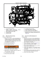
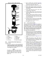
The compressor or any of the components attached to
it (high pressure switch, oil, etc.) may be serviced or
replaced by pumping the compressor down, and isolat-
ing the compressor from the rest of the system.
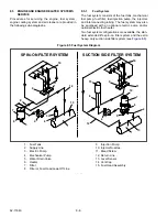
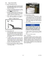
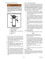
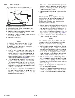
1. Install a manifold gauge set to allow reading of
suction and discharge pressure. See
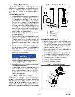
2. If the compressor is operational, start the unit
and slowly frontseat the suction service valve.
shutdown the unit when the suction pressure
drops to 2 psig (0.2 bar). Ensure the unit will not
start automatically by disabling any two way
communication and placing the STOP/RUN-
OFF switch in the OFF position. Disconnect the
high voltage source and lockout/tagout the
receptacle. Frontseat the discharge service
valve to isolate compressor. There should be
very little refrigerant remaining in the compres-
sor at this point.
3. If the compressor is not operational, ensure the
unit will not start automatically by disabling any
two way communication and placing the STOP/
RUN-OFF switch in the OFF position. Discon-
nect the high voltage source and lockout/tagout
the receptacle. Frontseat both the discharge
and suction service valve to isolate the com-
pressor.
4. Connect a refrigerant recovery device and a
clean refrigerant recovery cylinder to the suction
and discharge service valves and remove any
remaining refrigerant from the compressor. DO
NOT bring the compressor pressure below 0
psig/bar.
5. After making necessary repairs, leak check and
evacuate the compressor. (Refer to
and
f. Adjusting The Charge Level
Adjustment of the charge level may be required when
there has been a leak or the system was not correctly
charged during a previous service.
1. Check charge level by performing the proce-
dures of the preceding step a.
2. If charge removal is required: connect a clean
evacuated refrigerant recovery cylinder to the
liquid line service valve. Open liquid valve on
cylinder. Midseat liquid line service valve and
monitor the liquid refrigerant flow into the cylin-
der. If the unit is operating, close the cylinder
valve and backseat the liquid line service valve
when the ball in the upper sight glass drops to
the bottom of the glass. If the unit is not operat-
ing, when approximately 5 lbs. (2.3 kg) have
been removed close the cylinder valve and
backseat the liquid line service valve. Proceed
to step 7.
3. If charge is to be added: place cylinder of refrig-
erant on a scale and connect a charging line
and gauge from cylinder to liquid line service
valve. Start unit in Continuous Operation with a
setpoint lower than refrigerated compartment
temperature. Wait until unit switches to high
speed operation. Run approximately ten min-
utes.
4. Note weight of cylinder and refrigerant.
5. Frontseat the liquid line service valve (turn
clockwise) and watch the pressure on the mani-
fold gauge. When the pressure falls below the
pressure in the refrigerant cylinder [or to 50 psig
(3.4 bar)], open the cylinder valve and monitor
the liquid refrigerant to flow into the unit.
6. When approximately 5 lbs. (2.3 kg) have been
added, close the cylinder valve, and backseat
the liquid line service valve.
7. Recheck for the correct refrigerant charge.
(Refer to preceding step a.) Repeat preceding
steps as required. When charge level adjust-
ment is complete, remove refrigerant service
equipment.
g. Adding a Complete Charge
1. Evacuate unit and leave in deep vacuum. (Refer
.)
2. Determine charge required for this unit (refer to
the model/serial number nameplate or
) and procure a refrigerant cylinder with suffi-
cient weight of refrigerant. Place cylinder on
scale and connect charging line from cylinder to
liquid line service valve.
3. Note weight of cylinder and refrigerant.
4. Open the liquid valve on cylinder. Midseat liquid
line service valve and allow liquid refrigerant to
flow into the unit until the correct weight of refrig-
erant has been added.
NOTE
It is possible that all the required liquid may
not be pulled into the receiver, as outlined in
step 4. In this case, add the additional refrig-
erant in accordance with the charge adjust-
ment procedures, refer to preceding step f.
5. When scale indicates the correct charge has
been added, close liquid valve on cylinder and
backseat the liquid line service valve. Remove
charging hose.
6. Start unit and run Pretrip to check operation.
Summary of Contents for Vector 8500
Page 23: ...62 11640 1 6 1 3 SAFETY DECALS ...
Page 24: ...1 7 62 11640 62 03958 ...
Page 25: ...62 11640 1 8 ...
Page 26: ...1 9 62 11640 ...
Page 27: ...62 11640 1 10 ...
Page 125: ...62 11640 SECTION 6 MESSAGECENTER PARAGRAPH NUMBER Page 6 1 MESSAGECENTER MESSAGES 6 1 ...
Page 321: ......
Page 322: ......


