8–25
62-11640
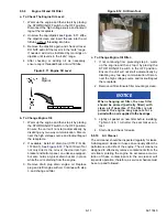
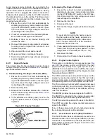
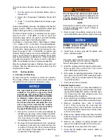
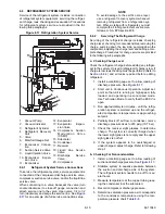
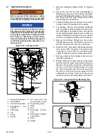
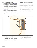
Figure 8.20 Condenser/Radiator Assembly
1. Condenser/Radiator Assembly
2. Condenser Frame
3. Condenser Coil
4. Radiator
5. Radiator Frame
6. Ambient Air Temperature Sensor (ATT)\
7. Condenser/Radiator Assembly Mounting
Bolts
8. Radiator Frame Mounting Bolts
9. Radiator Mounting Brackets
10. Condenser Coil Mounting Brackets
- - - - -
8.8.3
Filter-Drier
a. Check Filter-Drier
The unit must be running in cool for this test. Check for
a restricted or plugged filter-drier by feeling the liquid
line inlet and outlet connections of the drier cartridge.
If the outlet side feels cooler than the inlet side, then
the filter-drier should be replaced.
b. Replace Filter-Drier
1. Pump down the low side. Refer to
2. Remove bracket, loosen the inlet connection to
relieve any remaining pressure then remove
drier.
3. Procure new O-rings. Lubricate the O-rings,
back side of sleeves and coupling nuts. Using a
backup wrench at each connection torque 30 to
38 ft/lbs (40.7 to 51.5 Nm).
4. Leak check, evacuate & dehydrate, and charge
system as required. Refer to
,
&
8.8.4
Replacing Receiver Sight Glass Or Fus-
ible Plug
1. Remove the refrigerant charge. Refer to
2. Loosen the sight glass or fusible plug to relieve
any remaining pressure. Remove and discard
glass or plug.
3. Using new o-ring, install component. Torque the
sight glass to 15 to 25 ft/lbs (20.3 to 33.9 Nm).
Torque the fusible plug to 48 to 96 inch/lbs (5.4
to 10.8 Nm).
4. Leak check, evacuate & dehydrate, and charge
system as required. Refer to
,
&
Summary of Contents for Vector 8500
Page 23: ...62 11640 1 6 1 3 SAFETY DECALS ...
Page 24: ...1 7 62 11640 62 03958 ...
Page 25: ...62 11640 1 8 ...
Page 26: ...1 9 62 11640 ...
Page 27: ...62 11640 1 10 ...
Page 125: ...62 11640 SECTION 6 MESSAGECENTER PARAGRAPH NUMBER Page 6 1 MESSAGECENTER MESSAGES 6 1 ...
Page 321: ......
Page 322: ......

