8–37
62-11640
8.9.7
Light Bar
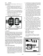
The light bar may be tested using a 12 VDC source. To
test the light bar:
1. Connect the ground (-) from the power source to
pin G on the light bar side of the connector.
2. The green LED’s will illuminate when the 12
VDC side (+) of the power source is connected
to pin B.
3. With the connection as in the preceding steps (+
on pin B, and - on pin G), the amber LED’s will
illuminate when the power (+) from the power
source is also connected to pin H.
4. Start unit and run Pretrip to check operation.
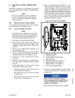
Figure 8.33 Light Bar Connections
8.9.8
Overload Ground Fault (OGF)
a. Operation
The OGF is designed to detect current overload and
fault to ground in the AC voltage circuits. The function
of the OGF is to shut down the power supply (genera-
tor or standby) when current is over 40 amp for 2 sec-
onds, or leakage to ground is more than 150mA.
Power, from HVB1K, energizes the OGF at terminal
+12 V. The module is grounded by the microprocessor
at the OV terminal through SP50.
This power also flows through the OGF normally
closed contacts and the S+ terminal through SP63 to
2CCB. If an overload or excessive leakage to ground
condition exists, the OGF contacts open to de-energize
and stop the flow of power to CCB1. Loss of power at
CCB1 activates the A00100 - “OVERLOAD/GROUND
FAULT” alarm.
b. OGF Checkout Procedure
1. Check the FAULT LED on the module. If the
LED is illuminated the module has activated and
12 VDC power supply is correct. Perform a meg-
ohm test (refer to
) to determine if
a fault to ground exists. This test will also help
determine if an excessive current condition
exists due to leakage to ground. Repair wiring or
components as required.
2. If AL00100 alarm is present and the fault LED
(on the module) is not illuminated, it means that
the module has detected an overcurrent. Verify
the current readout on the unit data.
If current readings are not reading correctly,
the current sensor may be at fault. Go to
step 5 & 6 to check the current sensor.
3. If a problem with the module is suspected,
check for 12VDC power to the module at the
+12V terminal and ground at the OV terminal.
Correct wiring as required. Reset module by
placing the Main Power switch in the OFF posi-
tion and then back in the desired position.
Check for 12 VDC at the S+ terminal. If LED is
off and the module normally closed connection
is open, replace module.
4. If module is OK, check for 12 VDC at SP63.
5. Check wiring between CT and pins 1CCB10,
1CCB12, 1CCB31, and 1CCB34 as required.
6. If a problem with the current sensors is sus-
pected, check sensor output. Current sensor
inputs to the module are rated at 16.7mV per
Amp. For every Amp that is read at the wires
coming from the GENCON or PSCON T1, T2
and T3 terminals with an amp meter, there
should be a corresponding voltage reading on
the blue, brown & orange wires to the black
wire. For example: 20Amps = 0.33VAC.
7. Sensor resistance should also be checked, all
wire must be disconnected. Check from Black to
each phase:
Black to Orange
−
22 ohms
Black to Blue
−
22ohms
Black to Brown
−
22 ohms
If any resistance values are not within
proper range (22 ohms) it indicates a defec-
tive sensor.
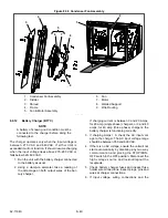
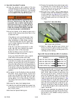
Figure 8.34 Overload Ground Fault Connections
A
H
E
F
G
D
C
B
LIGHT BAR
SIDE
CONTROL BOX
SIDE
A
H
E
F
G
D
C
B
GROUND
FAULT
S+
+12V
OV
L1
L2
L3
BLUE
BROWN
ORANGE
BLACK
TO CURRENT
SENSORS
S+
OV
+12V
Summary of Contents for Vector 8500
Page 23: ...62 11640 1 6 1 3 SAFETY DECALS ...
Page 24: ...1 7 62 11640 62 03958 ...
Page 25: ...62 11640 1 8 ...
Page 26: ...1 9 62 11640 ...
Page 27: ...62 11640 1 10 ...
Page 125: ...62 11640 SECTION 6 MESSAGECENTER PARAGRAPH NUMBER Page 6 1 MESSAGECENTER MESSAGES 6 1 ...
Page 321: ......
Page 322: ......


