8–39
62-11640
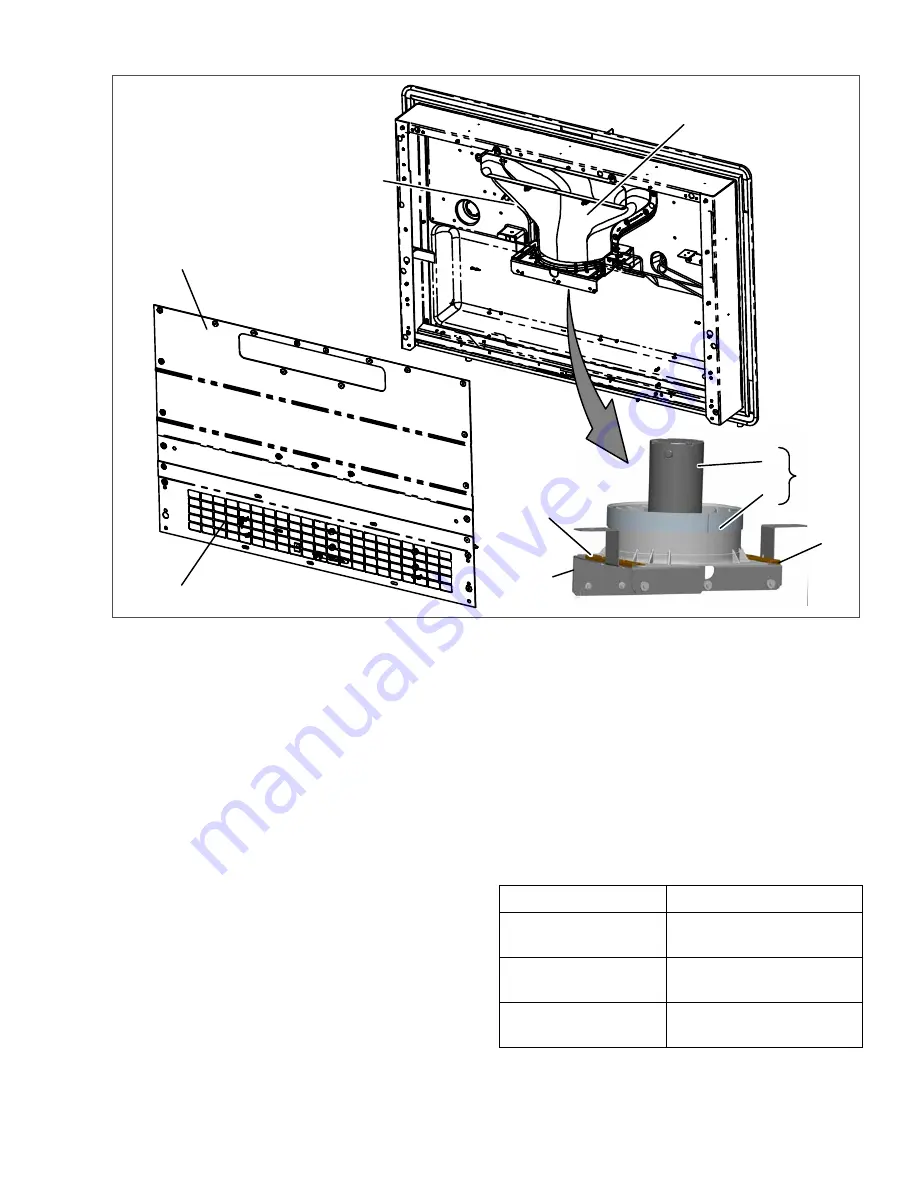
Figure 8.35 Evaporator Blower Assembly
1. Access Panel
2. Grille
3. Nozzle
4. Supply Air Sensor
5. Blower Assembly
6. Motor
7. Stator
8. Mounting Brackets
9. Support Bracket
- - - - -
8.9.11
Condenser Fan Assemblies
1. Ensure the unit will not start automatically by
disabling any two way communication and plac-
ing the STOP/ RUN-OFF switch in the OFF
position. Disconnect the high voltage source
and lockout/tagout the receptacle.
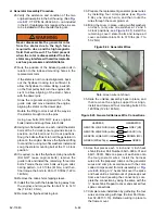
2. Disconnect the motor electrical connector. Note
motor is assembled to allow routing of the wiring
down the lower right hand leg of the welded sup-
port. See
3. Remove the condenser fan assembly mounting
bolts and slide the assembly out of unit. If
required, the divider may be removed by remov-
ing the upper and lower mounting bolts.
4. Disassemble the fan and motor assembly from
the mounting and then disassemble the fan from
the motor as required.
5. Complete the assembly in reverse order of
removal. When mounting fan & motor assembly,
assemble so wire connector is in line with lower
right welded support leg, see in
Torque:
Fan to motor bolts
4 to 6 ft/lbs (5.5 to 6.8 Nm)
Fan & motor assembly
to welded support bolts
5 to 6 ft/lbs (6.8 to 8.1 Nm)
Welded support to
frame bolts
7 to 8 ft/lbs (9.5 to 10.8 Nm)
Shroud to frame and
frame to unit bolts
6 to 7 ft/lbs (8.1 to 9.5 Nm)
Summary of Contents for Vector 8500
Page 23: ...62 11640 1 6 1 3 SAFETY DECALS ...
Page 24: ...1 7 62 11640 62 03958 ...
Page 25: ...62 11640 1 8 ...
Page 26: ...1 9 62 11640 ...
Page 27: ...62 11640 1 10 ...
Page 125: ...62 11640 SECTION 6 MESSAGECENTER PARAGRAPH NUMBER Page 6 1 MESSAGECENTER MESSAGES 6 1 ...
Page 321: ......
Page 322: ......


