62-11640
8–42
c. Generator Removal
1. Ensure the unit will not start automatically by
disabling any two way communication and plac-
ing the STOP/RUN-OFF switch in the OFF posi-
tion. Disconnect the high voltage source and
lockout/tagout the receptacle, refer to
, SAFETY PRECAUTIONS.
2. Remove the front roadside and curbside doors.
3. Disconnect the negative battery cable from the
battery.
4. Disconnect the positive battery cable from bat-
tery.
5. Remove the tie wraps holding the connectors to
the intake hose at the intake manifold connec-
tion. Disconnect the air intake hose from the
intake manifold.
6. Remove any brackets securing the positive and
negative battery cables to the unit (the brackets
may remain clamped to the cables).
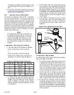
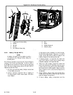
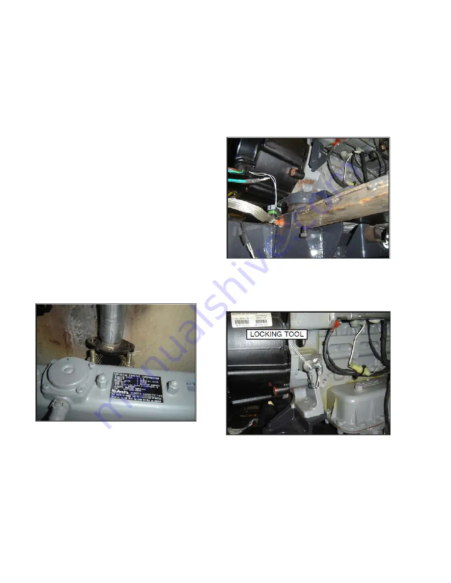
7. Remove the heat shield from the exhaust con-
nection at the manifold (see
) and
then remove the hardware holding the exhaust
to the manifold.
8. Remove the radiator hose “p” clamp.
9. Remove the tie wraps holding the generator
connections to the frame mount.
Figure 8.38 Exhaust Connection Disassembly
10. If equipped, disconnect the Generator Thermis-
tor.
11. Remove the hardware attaching the generator
ground strap at the frame and the harness
ground wire at the back of the generator.
12. Pull the fuel lines from the back of the Engine in
order to provide slack so that the lines are not
damaged when the unidrive assembly is pulled
forward.
13. Remove the two engine mounts at the generator
end of the unidrive.
14. Remove engine end unidrive mount at the rear,
(toward trailer) and then loosen the remaining
unidrive mount sufficient to allow the unidrive to
rotate.
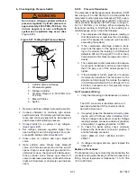
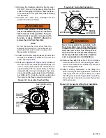
15. Install the support tool (Carrier Part Number
86
−
04751
−
00) under the back of the unidrive
(see
). Secure the tool in place, so it
will not pull out as the unidrive is rotated, by
installing a ½
−
13 bolt in the threaded hole pro-
vided.
Figure 8.39 Support Tool Secured, Bottom View
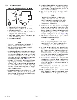
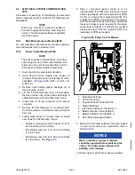
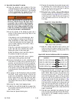
16. To prepare for removal of the rotor bolts, install
the flywheel locking tool (Carrier Part Number
07
−
60083
−
,
Figure 8.40 Flywheel Locking Tool
17. Swing the unidrive assembly out sufficient to
remove the generator.
18. Remove the tape from the generator splice con-
nections.
TIP
When cutting the generator splices, cut on the
harness side, leaving just enough harness wire
so that the wiring remaining on the old genera-
tor may be viewed later to determine color
combinations required for reassembly.
19. Cut the generator splices from the harness.
Summary of Contents for Vector 8500
Page 23: ...62 11640 1 6 1 3 SAFETY DECALS ...
Page 24: ...1 7 62 11640 62 03958 ...
Page 25: ...62 11640 1 8 ...
Page 26: ...1 9 62 11640 ...
Page 27: ...62 11640 1 10 ...
Page 125: ...62 11640 SECTION 6 MESSAGECENTER PARAGRAPH NUMBER Page 6 1 MESSAGECENTER MESSAGES 6 1 ...
Page 321: ......
Page 322: ......

