62-11640
8–44
d. Generator Assembly Procedure
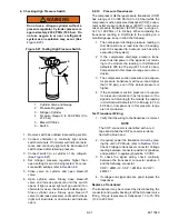
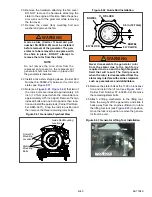
26. Verify the existence and condition of the two
original dowel pins in the bell housing. (See
−
06329
−
00
−
not included
in the kit. If replacement is required, the pins are
to be installed with the chamfer facing out.
WARNING
!
Never disassemble the generator rotor
from the stator due to the high force
required to do so and the high magnetic
field that will result. The field present
when the rotor is disassembled from the
stator may interfere with cardiac implants
such as pacemakers and defibrillator.
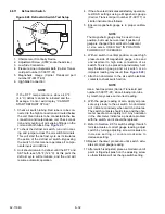
27. Note the position of the indexed guide rods in
relation to the indexed mounting holes in the
replacement rotor.
If the stator is not in correct alignment, back
out the flywheel locking tool sufficient to
allow the flywheel to rotate. Using a wrench
on the front pulley bolt, turn the engine suffi-
cient to allow aligning of the stator holes
with the dowel pins.
Slide the replacement generator on the
guide rods and move towards the engine,
aligning the stator on the dowel pins
Rotate the lifting tool lock out of the way as
the stator is brought onto the pins.
Using new bolts (DO NOT reuse original
bolts) install and snug three rotor bolts.
28. Using two flat washers on each, install the stator
bolts at the 5 o’clock (ensure ground strap is in
position on this bolt) and 8 o’clock positions.
Snug the bolts sufficient to hold the generator in
place on the engine. Remove the flywheel lifting
tool and then, using two flat washers install and
snug the stator mounting bolt at the 11 o’clock
position.
29. If required, re
−
lock the flywheel. Using new bolts
(DO NOT reuse original bolts), remove the
guide rods and install the remaining three rotor
bolts. Torque the six rotor bolts, using an alter-
nating pattern, to 45 ft/lbs (61 Nm) and then,
final torque the bolts to 90 to 110 ft/lbs (122 to
149 Nm).
30. Remove the mica shim shipping sleeve.
31. Install the fan (with the blades facing away from
the engine) and torque the fan bolt 12 to 14 ft/
lbs (16.3 to 19 Nm).
32. Remove the flywheel locking tool.
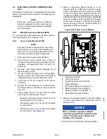
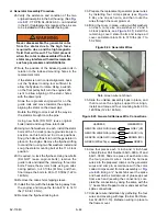
33. Prepare the replacement generator power wires
by installing four crimp splices (see
), one on each wire, and then route the
wires through the cover grommet.
34. Bring the cover in place, using two flat washers
on each, (only use one washer at 2 and 5
o’clock positions, see
) install the
remaining cover/ stator bolts and torque all
cover and stator blots 33 to 37 ft/lbs (44.7 to
50.2 Nm).
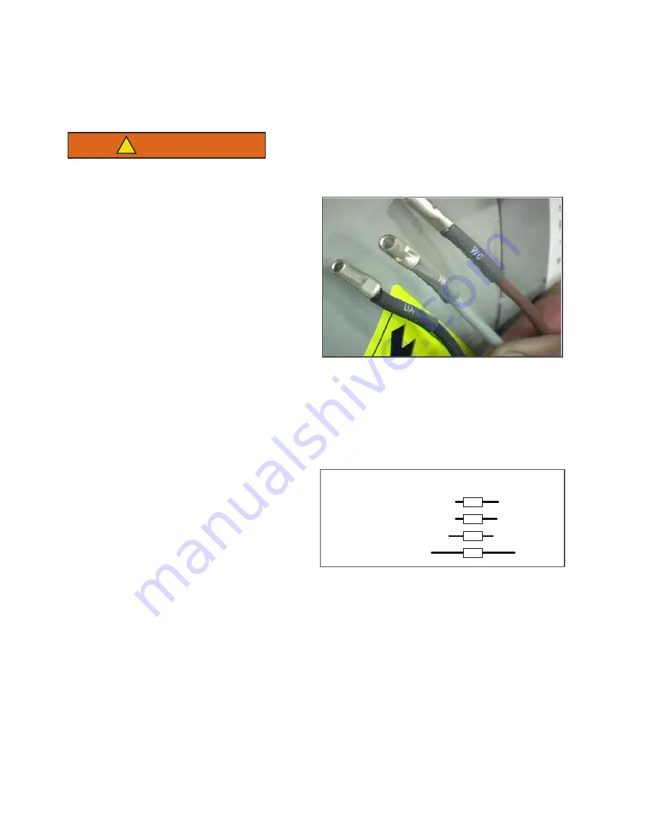
Figure 8.44 Generator Wires
Note: Green wire not shown
35. Slide the unidrive assembly back in place, and
then remove the engine support tool. Align,
install and torque all four mounting bolts 90 to
120 ft/lbs (122 to 163 Nm).
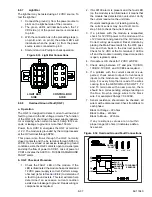
Figure 8.45 Generator/Harness Wire Connections
36. Use four pieces each ¼ inch and ½ inch heat
shrink (Carrier Part Number 66U1
−
3803
−
01 and
66U1
−
3803). Slide one piece of each size onto
the four generator wires. Install the harness
wires into the prepared crimps on the generator
wires and crimp in accordance with the color
coded crimps saved from dis
−
. Bring a ¼” heat shrink over the splice
and heat until a small amount of glue seeps out
from each end (sealing the connection), com-
plete the connection by doing the same with the
½” heat shrink. Repeat to cover and seal all four
splice connections.
37. Complete wire installation by gathering the four
wires and covering with tape (Carrier Part Num-
ber 02
−
00137
−
10). Refasten wiring in place to
the frame mount.
GENCON L1/GEN VB (black)
GENCON L2/GEN UA (white)
GENCON L3/GEN WC (red)
GREEN (W/Red Tape)
HARNESS
GENERATOR
GREY (VB)
BLACK (UA)
BROWN (WC)
GREEN
Summary of Contents for Vector 8500
Page 23: ...62 11640 1 6 1 3 SAFETY DECALS ...
Page 24: ...1 7 62 11640 62 03958 ...
Page 25: ...62 11640 1 8 ...
Page 26: ...1 9 62 11640 ...
Page 27: ...62 11640 1 10 ...
Page 125: ...62 11640 SECTION 6 MESSAGECENTER PARAGRAPH NUMBER Page 6 1 MESSAGECENTER MESSAGES 6 1 ...
Page 321: ......
Page 322: ......


