62-11640
2–10
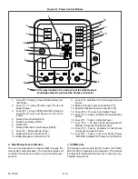
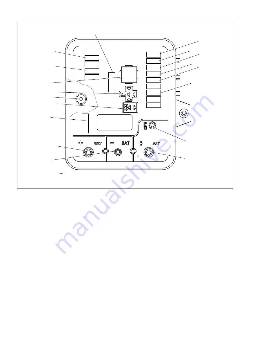
Figure 2.5 Power Control Module
1. Fuse (F5 = 30 amp), Power Enable Relay Con-
tact Power
2. Fuse (F1 = 5 amp), Module Logic Circuit and
Buzzer Power
3. Fuse (F3 = 5 amp), 2SVM & 3SVM Component
Actuation Power and Engine Control Unit
Power
4. Relay, Power Enable (PER)
5. Relay, Fuel Heater (FHR)
6. Buzzer (B)
7. Relay, AutoFresh Air Exchanger (AFAR)
8. Fuse (F7 = 80 amp) Main Power
9. Battery Positive Connection (T1)
10. Battery Negative Connection (T2)
11. Fuse (F6), AutoFresh Air Exchange Solenoid
Power
12. Battery Charger Output Connection (T3)
13. Engine Preheater Power Connection (T4)
14. Fuse (F14 = 15 amp), Fuel Heater Power
15. Fuse (F12 = 5 amp), Satellite Communications
Power
16. Fuse (F11 = 5 amp), Light Bar Power
17. Fuse (F10 = 20 amp), Main Microprocessor
Module Component Actuation Power
18. Fuse (F9 = 5 amp), Contactor Control Board
Component Actuation Power
19. Fuse (F8* = 5 amp), Fuel Level Sensor Power
*With EES installed F8=10 amp for FLS & EES
- - - - -
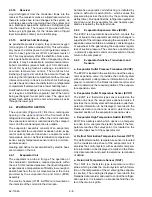
b. Main Microprocessor Module
The main microprocessor module (MM) houses the
main system microprocessor. The module is totally self
contained and does not contain any serviceable com-
ponents.
c. SVM Module
The stepper valve module (SVM) houses the CSMV,
EVXV & ECXV operating microprocessor. The module
is totally self contained and does not contain any ser-
viceable components.
F9
F5
F1
F3
F8
F10
K1
K2
K3
F12
F14
F11
F6 (10 amp) located in the white wire at the AutoFresh air
exchange solenoid, just past the harness connector.
F7
Summary of Contents for Vector 8500
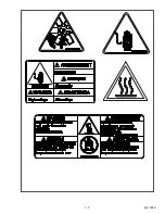
Page 23: ...62 11640 1 6 1 3 SAFETY DECALS ...
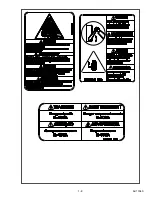
Page 24: ...1 7 62 11640 62 03958 ...
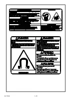
Page 25: ...62 11640 1 8 ...
Page 26: ...1 9 62 11640 ...
Page 27: ...62 11640 1 10 ...
Page 125: ...62 11640 SECTION 6 MESSAGECENTER PARAGRAPH NUMBER Page 6 1 MESSAGECENTER MESSAGES 6 1 ...
Page 321: ......
Page 322: ......

