7–1
62-11640
SECTION 7
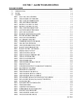
ALARM TROUBLESHOOTING
WARNING
!
APX control system equipped units may
start automatically at any time the
START/ RUN-OFF switch is in the START/
RUN position. Also, the unit may be fitted
with two way communication equipment
that will allow starting of the unit from a
remote location even though the switch
is in the OFF position.
WARNING
!
When performing service or maintenance
procedures: ensure any two way commu-
nication is disabled in accordance with
the manufacturer’s instruction, ensure
the START/RUN-OFF switch is in OFF
position and, whenever practical, discon-
nect the negative battery connection.
7.1
INTRODUCTION
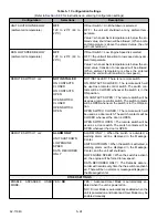
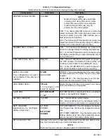
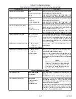
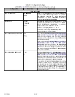
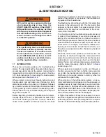
This section provides guidance for troubleshooting
alarms. The alarm light will be illuminated when there is
at least one alarm stored in the system. Instructions for
reviewing the active alarm list are provided in
while instructions for reviewing the inactive alarm
list are provided in
When an alarm occurs, look through both active and
inactive alarm lists and make note of all alarms. Each
alarm begins with an A (active) or I (inactive) followed
by an alarm number and description. Alarms are listed
in this guide by alarm number in ascending order.
Alarms that are only activated during a Pretrip will
begin with a capital “P”.
Before beginning to actually troubleshoot an alarm,
visually inspect the unit, in particular the area of the
unit that is causing a problem. In many cases the
cause of the problem will be obvious once a visual
inspection is performed. For those cases where the
cause of the problem is not obvious, this troubleshoot-
ing guide will be of assistance.
Troubleshooting should begin with the first alarm that
appears in the active alarm list. The first alarm that
appears is the last alarm that was recorded. Other
alarms in the list may have contributed to the occur-
rence of the first alarm.
The check items in the troubleshooting guide are listed
in order of their likeliness of occurrence and ease of
testing. We recommend that you follow the order in
which they are presented, however, there may be times
when situations or experience lead to the use of a dif-
ferent order. For example, if the trailer is loaded, con-
densing section checks should be done first, even
though some evaporator section checks may be listed
before them.
When the cause of the problem is corrected, it is not
necessary to continue through the remainder of the
steps. Some active alarms will inactivate themselves
automatically once the cause has been corrected.
Alarms that do not inactivate themselves automatically
must be cleared manually. (Refer to Note 1 in
Section, page 7-2)
When repairs are completed, run the unit through a
Pretrip cycle and verify that no further active alarms
occur. Also, the inactive alarm list should be cleared so
that there are no inactive alarms in memory when the
unit leaves the repair facility.
When working on the refrigeration system, an accu-
rately calibrated manifold gauge set should always be
installed, set up to read compressor suction and dis-
charge pressure. Compressor suction pressure is dis-
played under Unit Data when in the Driver Mode. If in
the Advance User Mode, compressor discharge pres-
sure and temperature will also be displayed.
In high or low ambient it may be necessary to cool or
warm the refrigerated compartment temperature before
performing specific tests providing that the compart-
ment is not loaded with temperature sensitive product.
Summary of Contents for Vector 8500
Page 23: ...62 11640 1 6 1 3 SAFETY DECALS ...
Page 24: ...1 7 62 11640 62 03958 ...
Page 25: ...62 11640 1 8 ...
Page 26: ...1 9 62 11640 ...
Page 27: ...62 11640 1 10 ...
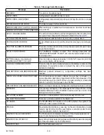
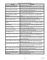
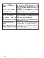
Page 125: ...62 11640 SECTION 6 MESSAGECENTER PARAGRAPH NUMBER Page 6 1 MESSAGECENTER MESSAGES 6 1 ...
Page 321: ......
Page 322: ......

