62-11640
7–104
P11000
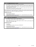
CHECK CONDENSER FAN MOTOR 2
• ACTIVATION: Normal draw for the condenser fan motors is 0.8 to 3.5 Amps (460 VAC). The circuit tests
outside this range.
• UNIT CONTROL: Engine and Electric Operation: Pretrip will fail and display “PRETRIP FAIL AND COM-
PLETED”.
• RESET CONDITION: Auto Reset if Pretrip is started again, or alarm may be manually reset via keypad or
by turning the unit off, then back on again.
CORRECTIVE ACTIONS:
1. Check Motor - refer to procedure for Alarm
P00190 CHECK CONDENSER FAN MOTOR
P13000
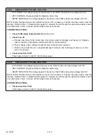
CHECK CONDENSER FAN 2 CIRCUIT
• ACTIVATION: Normal draw for the CDCON2 contactor coil is 0.05 to 2.0 Amps (12 VDC). The circuit
tests outside this range.
• UNIT CONTROL: Engine and Electric Operation: Pretrip will fail and display “PRETRIP FAIL AND COM-
PLETED”.
• RESET CONDITION: Auto Reset if Pretrip is started again, or alarm may be manually reset via keypad or
by turning the unit off, then back on again.
CORRECTIVE ACTIONS:
1. Refer to procedure for Alarm
P00206 CHECK CONDENSER FAN CIRCUIT
20100
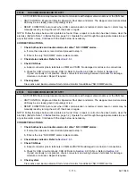
NO COMM FROM MICRO TO DISPLAY
NOTE
This alarm will be available in the inactive alarm list and download only. It is an indication that an
intermittent failure is occurring, causing a break in the circuit sufficient to activate the alarm.
• ACTIVATION: If alarm 21100 “NO COMM FROM ANY BOARD TO MAIN MICRO“ is not active and main
microprocessor cannot communicate with the display module over the CAN bus.
• UNIT CONTROL: Engine and Electric Operation: Required Shutdown. If alarm remains active for 2 minutes
issue a shutdown command to all modules except the display.
• RESET CONDITION: Auto reset when CAN communication is restored, or alarm may be manually reset by
turning the unit off, then back on again.
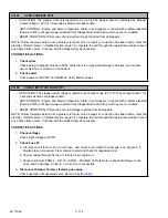
NOTE: Follow the steps below until a problem is found. Once a repair or correction has been made, clear the
alarm(s). (Refer to Note 1 in
Section, page 7-2.) Operate the unit through the appropriate modes to see if
any active alarm occurs. Continue with the steps below as necessary.
CORRECTIVE ACTIONS:
1.
Check CAN bus
a. Inspect connector pins & terminals on 1MM, 1SVM and DM. No damaged or corrosion in connections.
b. Check display LOSS OF COMMUNICATIONS message is displayed.
c. Check for CAN circuit continuity: CAN Hi; Refer to
. If
good continuity is not present, check connectors and wiring between terminals for damage, mois-
ture or corrosion.
Summary of Contents for Vector 8500
Page 23: ...62 11640 1 6 1 3 SAFETY DECALS ...
Page 24: ...1 7 62 11640 62 03958 ...
Page 25: ...62 11640 1 8 ...
Page 26: ...1 9 62 11640 ...
Page 27: ...62 11640 1 10 ...
Page 125: ...62 11640 SECTION 6 MESSAGECENTER PARAGRAPH NUMBER Page 6 1 MESSAGECENTER MESSAGES 6 1 ...
Page 321: ......
Page 322: ......


