8–5
62-11640
1. Ensure the unit will not start automatically by
disabling any two way communication and plac-
ing the STOP/RUN-OFF switch in the OFF posi-
tion. Disconnect the high voltage source and
lockout/tagout the receptacle.
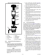
2. Remove the 3 grille insert mounting bolts on
each side of the grille insert, See
3. Remove the 2 grille insert mounting bolts on top
of the grille insert.
4. The grille is fitted with locating tabs along the
bottom. To remove, swing insert down and lift
out of locating slots.
5. Reverse above steps to install grille insert.
8.4.3
Surround Removal
NOTE
It is not necessary to remove the grille
before removing the surround.
1. Ensure the unit will not start automatically by
disabling any two way communication and plac-
ing the STOP/RUN-OFF Switch in the OFF posi-
tion. Disconnect the high voltage source and
lockout/tagout the receptacle.
2. Open both side and front doors.
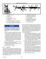
3. Remove the bolts that secure the surround to
4. Reverse above steps to install surround.
Figure 8.3 Surround Removal
8.4.4
Door Latch Maintenance and Replace-
ment
a. Door Latch Maintenance
Proper maintenance is important for smooth operation
of the latch assemblies and the latch pins that are
mounted on the unit’s frame (See
). In order
to keep the movable parts clean and lubricated, CTD
recommends the use of a de-greasing cleaner and LPS
2 lubricant. This lubricant should be available at any
local automobile and truck parts suppliers.
b. Cable Replacement
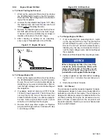
1. Remove circular clip that secures the cable to
the paddle assembly. See
2. Slide cable from paddle and rotate other end out
of latch assembly.
NOTE
The side door lower cable is inserted
through the upper cable eyelet. The lower
cable is to be removed to gain access to the
upper cable.
3. Reverse above steps to install new cable.
Figure 8.4 Door Latch Cable Removal
1. Paddle Assembly (Typical, Front & Side Doors)
2. Circular Clips (Typical, Front & Side Doors)
3. Lower Cable Upper Connection (Side Doors Only)
4. Upper Cable (Side Doors Only)
- - - - -
8.4.5
Display Module
Procedures for servicing the display module are pro-
vided in
.
MOUNTING BOLTS
MOUNTING BOLTS
REMOVE DECAL PLATE TO
ACCESS UNIT MOUNTING STUD.
Summary of Contents for Vector 8500
Page 23: ...62 11640 1 6 1 3 SAFETY DECALS ...
Page 24: ...1 7 62 11640 62 03958 ...
Page 25: ...62 11640 1 8 ...
Page 26: ...1 9 62 11640 ...
Page 27: ...62 11640 1 10 ...
Page 125: ...62 11640 SECTION 6 MESSAGECENTER PARAGRAPH NUMBER Page 6 1 MESSAGECENTER MESSAGES 6 1 ...
Page 321: ......
Page 322: ......

