8–15
62-11640
8.6
REFRIGERANT SYSTEM SERVICE
Service of the refrigerant system includes: connection
of refrigerant system equipment, servicing the refriger-
ant charge, leak checking and evacuation. Procedures
for refrigerant system service are provided in the fol-
lowing sub paragraphs.
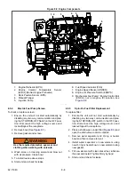
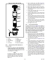
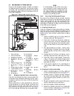
Figure 8.17 Refrigeration System Service
8.6.1
Refrigerant System Service Connections
To service the refrigerant system, service equipment is
connected at the compressor discharge service valve,
compressor suction service valve, and/or the liquid line
service valve.
When connecting to a valve, backseat the valve (turn
counterclockwise) to close off gauge connection and
attach service line to the valve. Open valve 1/4 to 1/2
turn (clockwise) and purge the service line. See
for an example of a full service connection setup.
NOTE
To avoid damage to the earth’s ozone layer,
use a refrigerant recovery system whenever
removing refrigerant from a refrigeration sys-
tem. When working with refrigerants you must
comply with all local government environmen-
tal laws, U.S.A. EPA section 608.
8.6.2
Servicing The Refrigerant Charge
Servicing of the refrigerant charge includes: checking
charge level, checking for noncondensibles, removing the
charge, pumping down the low side, pumping down the
compressor, adjusting the charge level and adding a com-
plete charge. Procedures for charge service are provided
in the following sub paragraphs.
a. Checking Charge Level
Check the refrigerant charge before adding any refriger-
ant to the system. Only add refrigerant if charge is low. If
charge is low, leak checking must be performed (Refer to
) and all leaks repaired before adding
refrigerant.
1. Install a manifold gauge set to allow reading of
2. Start unit in Continuous Operation. Adjust set-
point so that unit is running in high speed, fully
loaded, and operating in economized mode.
Use Technician Mode to verify that the ECXV is
open.
3. Run approximately ten minutes - until the refrig-
eration system is warmed up and the refriger-
ated compartment temperature is approaching
setpoint.
4. Partially block off air flow to condenser coil so
discharge pressure rises to 230 psig (15.7 bar).
5. Check the receiver sight glasses to determine
charge. The system is correctly charged when
the lower sight glass is not empty and the upper
sight glass is not full.
6. If the system appears to be overcharged or
under charged, adjust charge. Refer to following
step f.
b. Checking For Noncondensibles
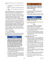
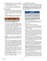
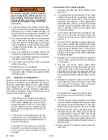
1. Install a manifold gauge set to allow reading of
suction and discharge pressure. See
2. Stabilize system to equalize pressure between
the suction and discharge side of the system.
The refrigerant system needs to be off for sev-
eral hours.
3. Measure temperature at the copper tubing leav-
ing the condenser (not the subcooler).
4. Record compressor discharge pressure.
5. Determine saturation pressure as it corresponds
to the condenser temperature using the tem-
perature pressure chart,
1. Vacuum Pump
2. Vacuum Indicator
3. Refrigerant Cylinder
4. Refrigerant Recovery
Unit
5. Valve
6. Manifold Gauge Set
7. Economizer Connec-
tion
8. Suction Service Valve
9. Liquid Injection Valve
10. Economizer Expan-
sion Valve
11. Economizer
12. Evaporator
13. Evaporator Expan-
sion Valve
14. Compressor Suction
M o d u l a t i o n Va l v e
(CSMV)
15. Subcooler
16. Condenser
17. Receiver
18. Liquid Line Service
Valve
19. Discharge Service
Valve
20. Compressor
Summary of Contents for Vector 8500
Page 23: ...62 11640 1 6 1 3 SAFETY DECALS ...
Page 24: ...1 7 62 11640 62 03958 ...
Page 25: ...62 11640 1 8 ...
Page 26: ...1 9 62 11640 ...
Page 27: ...62 11640 1 10 ...
Page 125: ...62 11640 SECTION 6 MESSAGECENTER PARAGRAPH NUMBER Page 6 1 MESSAGECENTER MESSAGES 6 1 ...
Page 321: ......
Page 322: ......

