8–23
62-11640
NOTE
Inspect the power plug terminals to ensure
they are not deformed or have any signs of
heat or arcing. If any damage is noted,
replace the power cable.
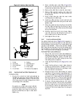
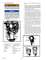
9. Remove (slide out) the old compressor from the
unit and slide the new compressor into the unit.
Refer to
.
NOTE
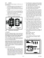
DO NOT add any oil to the replacement
compressor. Replacement compressor is
shipped with full oil charge of 60 oz.
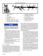
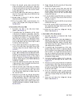
10. Install the “D” ring into the square groove of the
power plug.
11. Inject a small amount of lubricant (shipped with
the compressor) into each of the pin connec-
tions in the power plug. For ease of installation
and to prevent the “D” ring from rolling, use a
small amount of the lubricant to lubricate the
outside radius of the “D” ring.
12. Align the power plug with the cutout in the termi-
nal fence. Insert the power plug at a slight angle
allowing the “D” ring to start at the lower portion
of the terminal fence. Apply even pressure on
the back of the power plug until the flat surface
of the plug seats against the outer face of the
terminal fence. Insertion force of the power plug
to the compressor socket may be difficult, use of
a blunt hard object to pound compressor plug
into the compressor socket is not recom-
mended. Compressor pin damage may occur if
plugs are hammered into place. Use light tap-
ping from the palm of hand to aid in seating the
plug. If the plug is tight fitting, remove plug and
inspect the o
−
ring for proper seating in groove,
add more oil and retry.
13. Reinstall the plug retaining bracket or molded
plug retainer as required. Inspect that molded
plug retainer is fully engaged in the circle fence,
if not engaged correctly, insert the compressor
plug deeper into socket and verify the compres-
sor plug is inserted squarely to the socket.
14. Attach the compressor grounding terminal to the
compressor circle fence using new ground
screw provided. Grounding screw is a thread
cutting type screw.
NOTE
Due to thread cutting nature of the ground
screw, higher initial torque is required to “cut”
threads into the base metal. This high initial
torque can mislead one to believe the screw
is tight. Visually verify that screw is actually
providing a clamping pressure to the ground-
ing terminal and ring terminal is tight.
15. Install the four base
−
mounting bolts loosely.
16. Place new Teflon seals at the compressor suc-
tion and discharge ports. Apply a slight amount
of mineral oil (alkylated benzine oil CTD P/N
07
−
00274) to the economizer port O
−
ring, back
side of sleeves, and coupling nut and put in
place at the economizer line connection port.
Hand tighten all three connections.
17. Torque mounting bolts to 89 ft
−
lbs (66 Nm).
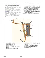
18. Using a backup wrench, torque the compressor
connections as follows:
19. Connect the new compressor discharge tem-
perature sensor (CDT) connector. Wire
−
tie any
loose wiring as appropriate.
20. Backseat the suction and discharge service
valves.
21. Reconnect the battery. With starter wire discon-
nected, place the unit back into “Service Mode”.
Leak check and evacuate the unit and charge,
refer to
.
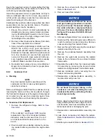
NOTICE
The scroll compressor achieves low suc-
tion pressure very quickly. Do not use the
compressor to evacuate the system
below 0 psig. Never operate the compres-
sor with the suction or discharge service
valves closed (frontseated). Internal dam-
age will result from operating the com-
pressor in a deep vacuum.
22. Following installation of a replacement compres-
sor, the oil level in the unit may be above the
required level. Adjust the oil level in accordance
with the instructions packaged with the replace-
ment compressor.
8.8
REFRIGERANT SYSTEM COMPONENT SER-
VICE
8.8.1
Evaporator Coil
The use of recycled cardboard cartons is increasing
across the country. The recycled cardboard cartons
create much more fiber dust during transport than
“new” cartons. The fiber dust and particles are drawn
into the evaporator where they lodge between the coil
fins. If the coil is not cleaned on a regular basis, some-
times as often as after each trip, the accumulation can
be great enough to restrict air flow, cause coil icing,
repetitive defrosts and loss of unit capacity.
Service Valve / Connection Torque Value
Suction and Discharge Ro-
talocks
80-100 ft-lbs (109-136
Nm)
Economizer Connection
38-42 ft-lbs (51-57
Nm)
Summary of Contents for Vector 8500
Page 23: ...62 11640 1 6 1 3 SAFETY DECALS ...
Page 24: ...1 7 62 11640 62 03958 ...
Page 25: ...62 11640 1 8 ...
Page 26: ...1 9 62 11640 ...
Page 27: ...62 11640 1 10 ...
Page 125: ...62 11640 SECTION 6 MESSAGECENTER PARAGRAPH NUMBER Page 6 1 MESSAGECENTER MESSAGES 6 1 ...
Page 321: ......
Page 322: ......

