62-11640
8–26
8.8.5
Economizer Heat Exchanger
1. Pump down the low side. Refer to
.
2. Ensure the unit will not start automatically by
disabling any two way communication and plac-
ing the STOP/RUN-OFF switch in the OFF posi-
tion. Disconnect the high voltage source and
lockout/tagout the receptacle.
3. Remove insulation, brackets and clamps from
economizer line assemblies as required (refer to
4. Remove the economizer expansion valve and
liquid injection solenoid valve coils.
5. Remove the economizer outlet pressure trans-
ducer and economizer outlet temperature sen-
sor.
6. Unbraze four lines at the economizer connec-
tions.
7. Note orientation of economizer (mounted with
connection markings upside
−
down). Remove
economizer heat exchanger, bolt replacement
economizer heat exchanger in place and
rebraze lines by reversing the previous steps.
8. Leak check, evacuate the unit and charge.
9. Reinstall the economizer outlet pressure trans-
ducer, economizer outlet temperature sensor,
valve coils and insulation.
10. Place unit back in service and check operation.
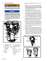
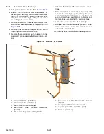
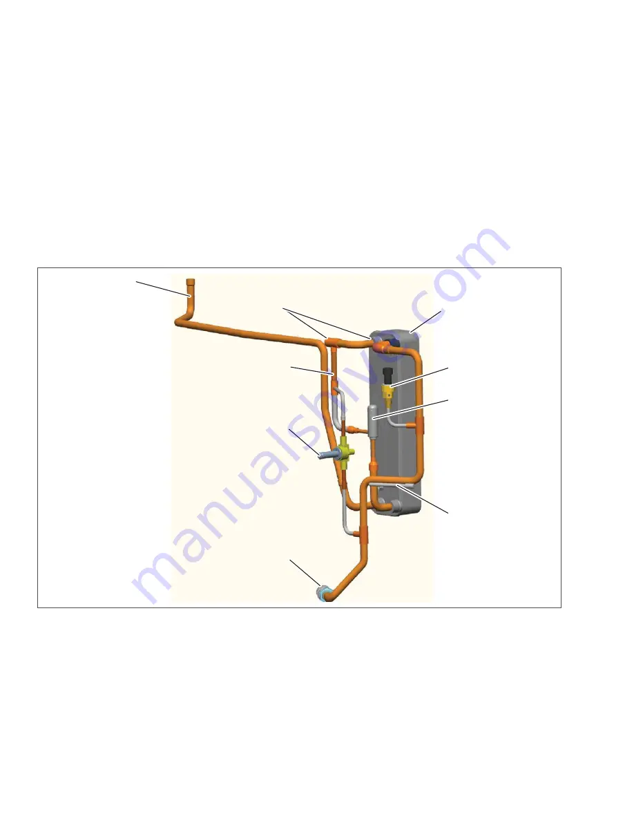
Figure 8.21 Economizer Section
1. Liquid Outlet Line (to EVXV)
2. Liquid Inlet Line (From Drier)
3. Economizer Heat Exchanger
4. Economizer Outlet Pressure Transducer
(ECOP)
5. Economizer Expansion Valve (ECXV)
6. Economizer Outlet Temperature Sensor
(ECOT)
7. Compressor Economizer Connection
8. Liquid Injection Solenoid Valve (LIV)
9. Strainer (Location)
- - - - -
4
Summary of Contents for Vector 8500
Page 23: ...62 11640 1 6 1 3 SAFETY DECALS ...
Page 24: ...1 7 62 11640 62 03958 ...
Page 25: ...62 11640 1 8 ...
Page 26: ...1 9 62 11640 ...
Page 27: ...62 11640 1 10 ...
Page 125: ...62 11640 SECTION 6 MESSAGECENTER PARAGRAPH NUMBER Page 6 1 MESSAGECENTER MESSAGES 6 1 ...
Page 321: ......
Page 322: ......

