62-11640
8–36
8.9.6
Megohmmeter Test Procedure
This instruction will aid in the check of the electrical
insulation integrity and connections using a resistance
tester (commonly known as a megohmmeter or Meg-
ger), such as Carrier Transicold part number
07
−
00481
−
00, that can be set to 1000V.
CAUTION
!
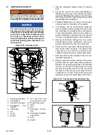
Before connecting a megohmmeter,
place the Main Power switch in the OFF
position. Disconnect the high voltage
source, lockout/ tagout the receptacle
and disconnect the negative battery con-
nection. Isolate the microprocessor by
disconnecting all connectors and wires
going to it. Observe National Electric
Manufacturer’s Association (NEMA) rules
and test equipment manufacturers
instructions.
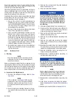
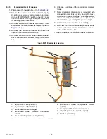
1. Disconnect the generator ground wire (GEN-
GRD = green wire marked with red tape) from
the unit ground plate (PE plate) inside the con-
trol box. See
. Fully insulate the
ground wire terminal with electrical tape.
2. Connect a tester lead to the ground plate.
Figure 8.32 Meghommeter Connection to Ground
Plate
3. Begin by testing the generator and interconnect-
ing wiring. To do this, connect the remaining tes-
ter lead to the GENCON contactor at terminal
L1. See
4. Set the tester to 1000V.
5. Press the tester TEST button and record read-
ing. It should be greater than 200 M If not, follow
the procedure outlined in Step h.
6. Continue testing the generator by testing at the
GENCON L2 and then the GENCON L3 termi-
nals. Both should measure greater than 200 M.
If not, follow the procedure outlined in Step h.
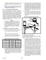
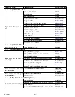
7. To complete the high voltage circuit testing, test
the T1, T2 and T3 terminals on all high voltage
contactors listed in
. The fuses and
the Overload Ground Fault Module (OGF) do
not need to be tested. All readings should be
greater than 200 M If not, follow the procedure
outlined in Step h. If all readings are 200 M or
greater, proceed to step i.
8. If a reading is less than 200 M reconnect the
generator ground wire, run the unit for 15 min-
utes to dry out the windings, remove and
re
−
insulate the generator ground wire and test
again. If the reading does not improve to above
200 M after running 15 minutes, check for a
short to ground by:
• Visually inspecting the tested component for any
poor connections or chafed wires.
• Isolating the component and wire harness.
• Retesting the harness and component (i.e. the
motor windings) with the megohmmeter to deter-
mine where the short to ground is located.
a. Following the completion of all testing, recon-
nect the generator ground wire at the unit
ground plate.
Summary of Contents for Vector 8500
Page 23: ...62 11640 1 6 1 3 SAFETY DECALS ...
Page 24: ...1 7 62 11640 62 03958 ...
Page 25: ...62 11640 1 8 ...
Page 26: ...1 9 62 11640 ...
Page 27: ...62 11640 1 10 ...
Page 125: ...62 11640 SECTION 6 MESSAGECENTER PARAGRAPH NUMBER Page 6 1 MESSAGECENTER MESSAGES 6 1 ...
Page 321: ......
Page 322: ......

