62-11640
8–40
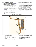
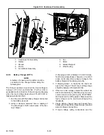
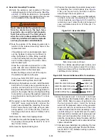
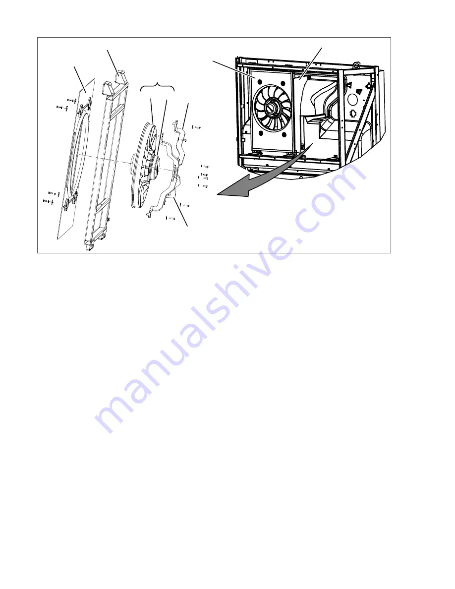
Figure 8.36 Condenser Fan Assembly
1. Condenser Fan Assembly
2. Divider
3. Shroud
4. Frame
5. Fan & Motor Assembly
6. Fan
7. Motor
8. Welded Support
9. Wire Routing
- - - - -
8.9.12
Battery Charger (BTYC)
NOTE
A battery of known good condition must be
connected to the charger before doing the
following test.
The charger operates only when the input voltage is
between 275 VAC and 640VAC. If either limit is
exceeded it will not function. It should resume charging
when the input voltage rises above 275
−
293 VAC or
falls below 620
−
630 VAC.
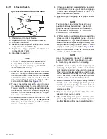
1. Run the unit with the battery charger connected
to the battery as usual.
2. Using a clamp-on ammeter, take a reading of
the amperage on both output wires of the bat-
tery charger.
If charging current is between 3 and 20 Amps,
for 20 amp (single phase) chargers, or 3 and 40
amps, for 40 amp (three phase) chargers, the
battery charger is functioning correctly.
3. If charging Amps = 0, check the AC input volt-
age to the charger. The AC input voltage range
should be between 350 and 600 VAC.
4. If there is no AC voltage, ensure the unit will not
start automatically by disabling any two way
communication and placing the STOP/RUN-
OFF switch in the OFF position. Disconnect the
high voltage source and lockout/tagout the
receptacle.
5. Check battery charger fuses and inspect fuse
holder wire connections. Inspect plugs, pins and
wires at charger connections.
6. If input voltage, wiring connections and the
4 PLCS.
Summary of Contents for Vector 8500
Page 23: ...62 11640 1 6 1 3 SAFETY DECALS ...
Page 24: ...1 7 62 11640 62 03958 ...
Page 25: ...62 11640 1 8 ...
Page 26: ...1 9 62 11640 ...
Page 27: ...62 11640 1 10 ...
Page 125: ...62 11640 SECTION 6 MESSAGECENTER PARAGRAPH NUMBER Page 6 1 MESSAGECENTER MESSAGES 6 1 ...
Page 321: ......
Page 322: ......

