62-11640
2–6
2.3
CONDENSING SECTION
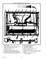
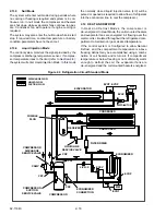
The condensing section (see
)
consists of an engine-generator drive package, com-
pressor, condenser fans, condenser, radiator, econo-
mizer, refrigerant controls, defrost air switch, piping,
wiring, and associated components. The condensing
section may also be equipped with an AutoFresh Air
Exchange.
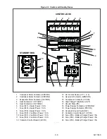
The engine-generator drive package (see
includes the engine, generator, air cleaner, muffler,
coolant system, fuel system, engine oil filter system
and engine sensors.
2.3.1
Engine
The engine is a four cylinder diesel which gives excel-
lent fuel economy. The engine cooling system consists
of the radiator (which is mounted with the condenser
coil) and coolant overflow bottle. The engine is
equipped with:
• an engine preheater (EPH), which provides easy
starting characteristics.
• spin-on engine oil filter and a spin
−
on or suction
side fuel filter for easier filter changes. The fuel
filter may also be equipped with a thermostati-
cally controlled fuel heater.
• an electronic battery charger which converts
generator or standby alternating current to direct
current for battery charging.
2.3.2
Engine Air System
The air cleaner prolongs the life and performance of
the engine by preventing dirt and grit from getting into
the engine and causing excessive wear on all operat-
ing parts. It is the responsibility of the operator to give
the air cleaner equipment regular and constant atten-
tion in accordance with the instructions. An air cleaner
service indicator is connected at the outlet. Its function
is to indicate when the air cleaner filter element
requires replacement. (Refer to
The system may be fitted with an intake air tempera-
ture sensor (IAT) and a manifold absolute pressure
transducer (MAP). These sensors are installed when
Carrier Transicold factory monitoring of the air system
is required.
2.3.3
Engine Controls
a. Fuel/Speed Actuator (FSA)
The FSA combines the fuel shutoff solenoid and speed
control solenoid into one component. Fuel supply to the
injectors and engine speed is controlled by varying rod
position in accordance with the signal from the control
system. In order to ease the load on the system, speed
transition (high to low and low to high) is ramped up or
down over a 10 second period. The FSA is located on
the front of the gear case cover.
b. Engine Speed Sensor (ENSSN)
The ENSSN provides the control system with informa-
tion on the speed at which the engine is running. The
ENSSN is located in the gear case cover above the
engine oil filter.
c. Rack Position Sensor (RPS)
The RPS provides the control system with engine fuel
rack (throttle) position information to be used to control
the engine and refrigeration system. The sensor is
located on the injection pump.
d. Engine Oil Pressure Switch (ENOPS)
The ENOPS is normally open and closes on pressure
rise to signal to the control system the engine has suffi-
cient oil pressure for operation. There is a 15 second
delay after the engine starts to allow the oil pressure to
build up before the control system looks at the input
from this switch. The switch is located in the oil filter
mounting assembly.
e. Engine Coolant Temperature Sensor (ENCT)
The ENCT is a thermistor type sensor that provides the
control system with engine coolant temperature infor-
mation to be displayed, recorded in the DataLink data
recorder and used to control the engine and refrigera-
tion system. The sensor is located on the starter side of
the engine near the #4 injector.
2.3.4
Generator (GEN)
The generator is directly bolted to the engine and sup-
plies nominal 460V/3Ø/60Hz power when the engine is
in high speed and nominal 345V/3Ø/45Hz power in low
speed.
The generator may be fitted with a generator tempera-
ture sensor (GNT). This sensor is installed when Car-
rier Transicold factory monitoring of the system is
required.
2.3.5
Compressor
The unit is fitted with a scroll compressor equipped with
suction and discharge service valves and an econo-
mizer connection. The compressor draws refrigerant
gas from the evaporator and delivers it to the con-
denser at an increased temperature and pressure. The
pressure is such that refrigerant heat can be absorbed
by the surrounding air at ambient temperatures.
Summary of Contents for Vector 8500
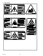
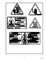
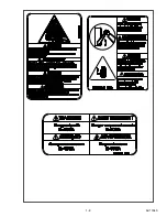
Page 23: ...62 11640 1 6 1 3 SAFETY DECALS ...
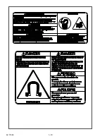
Page 24: ...1 7 62 11640 62 03958 ...
Page 25: ...62 11640 1 8 ...
Page 26: ...1 9 62 11640 ...
Page 27: ...62 11640 1 10 ...
Page 125: ...62 11640 SECTION 6 MESSAGECENTER PARAGRAPH NUMBER Page 6 1 MESSAGECENTER MESSAGES 6 1 ...
Page 321: ......
Page 322: ......

