2–11
62-11640
d. Microprocessor Status LED
Microprocessor activity within the main microprocessor
SVM Module or contractor control boards can be deter-
mined by observing the status LED’s. Module LED’s
are located just to the right of the module bar code
while contactor control board LED’S are visible through
small openings in the bottom mounting bracket.
An LED will:
• blink, green in color, once per second to indicate
that the microprocessor is operating correctly
• be off indicating no power to the module
• be on steadily, green in color, to indicate that the
microprocessor is not communicating (check
CAN bus)
• be on steadily, red in color, to indicate an internal
failure or loss of software.
e. Contactor Control Boards
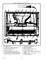
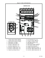
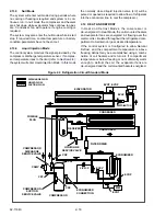
The contactor control boards (1CCB & 2CCB - see
) are slave boards that contain the necessary
software to control the contactors in accordance with
the unit model programmed into the main microproces-
sor. The boards communicate with the control system
through the CAN network.
f. AC Current Sensor
The current sensor (CT2, CT3 & CT4,
vides a reading of each individual AC line current draw
(amps) to the main microprocessor through the CAN
bus from 1CCB at terminals 1CCB
−
12,
−
34,
−
10 &
−
31
(see schematic diagram,
g. High Voltage Transformer (HVT)
The high voltage transformer (
) provides a
reading of line voltage to the main microprocessor
through the CAN bus from 1CCB at terminals
1CCB
−
19 &
−
35 (see schematic diagram,
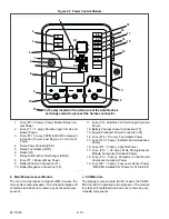
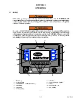
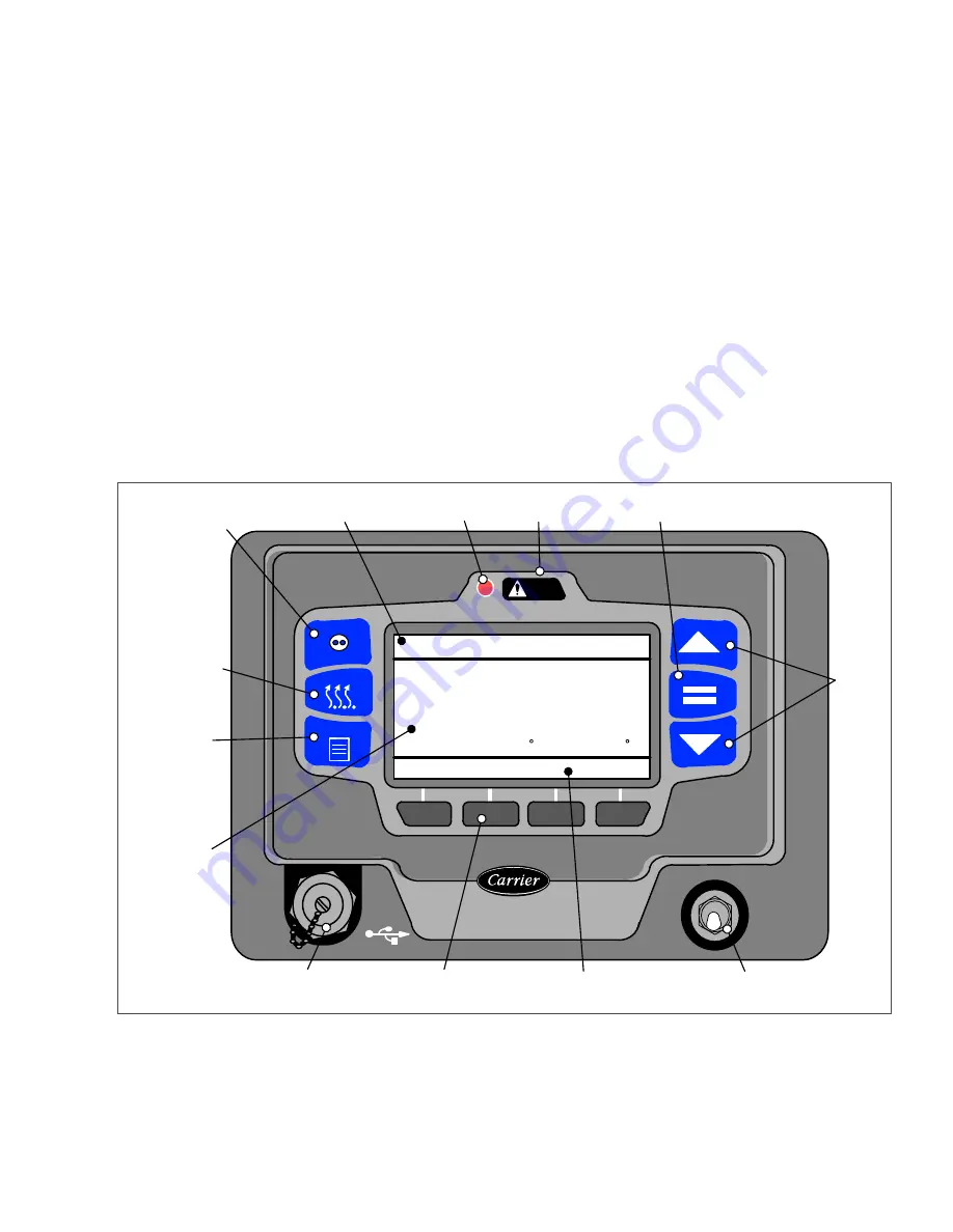
Figure 2.6 Display Module
h. Engine Control Unit (ENCU)
) is a microprocessor based unit
which controls the operation of the engine. The ENCU
communicates with the control system through the
CAN network and sends information on engine speed,
oil pressure and coolant temperature to the control sys-
tem to be displayed in the Advanced User Unit Data
and recorded in the DataLink data recorder. The ENCU
also communicates with the main microprocessor to
control overall system balance. The ENCU is mounted
on the frame near the fuel filter.
OFF
START/RUN
O
I
CONTINUOUS
START/STOP
MENU
ALARM
DEFROST
DIESEL
START/STOP
STATUS OK
36
36
.2
BOX TEMPERATURE F
SETPOINT F
LCD Display
MENU Key
DEFROST Key
START/STOP -
CONTINUOUS Key
Status Bar
Alarm LED
ALARM Key
= (Select) Key
Arrow
Keys
START/RUN-OFF Switch
MessageCenter
Soft Keys
USB Interface Port
Summary of Contents for Vector 8500
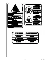
Page 23: ...62 11640 1 6 1 3 SAFETY DECALS ...
Page 24: ...1 7 62 11640 62 03958 ...
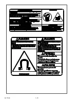
Page 25: ...62 11640 1 8 ...
Page 26: ...1 9 62 11640 ...
Page 27: ...62 11640 1 10 ...
Page 125: ...62 11640 SECTION 6 MESSAGECENTER PARAGRAPH NUMBER Page 6 1 MESSAGECENTER MESSAGES 6 1 ...
Page 321: ......
Page 322: ......


