62-11640
3–30
3.19 STOPPING THE UNIT
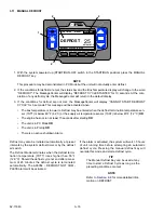
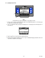
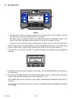
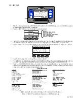
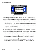
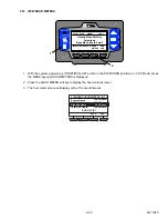
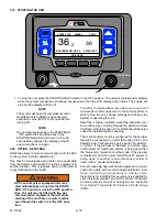
1. To stop the unit, place the START/RUN-OFF switch in the OFF position. The unit will shutdown immediately
while the system completes a shutdown sequence and then the LCD display will go blank. The engine will
stop and the display will turn off.
NOTE
The system will close the compressor suction
modulation valve (CSMV) and evaporator
expansion valve (EVXV) to 0% open before
turning off.
NOTE
Due to internal processing, the START/RUN
- OFF switch OFF and then back to the
START/RUN position will result in a 4 to 50
second delay between the display going off
and coming back on again.
3.20 OPTION - DATATRAK
DataTrak allows remote communication with the APX
control system (cellular, satellite, etc).
One Way Communication providers can request data
from the System and transmit it via their equipment to
another location. This is typically done via the Internet
to any destination in the world.
WARNING
!
APX control system equipped units may
start automatically at any time the START/
RUN - OFF switch is not in the OFF position.
Also, the unit may be fitted with two way
communication equipment that will allow
starting of the unit from a remote location
even though the switch is in the OFF posi-
tion.
Two Way Communication providers can also send
commands via their equipment to the control system to
start or stop the unit, change settings and the way the
System is operating the unit.
DataTrak is factory installed. DataTrak installation can
be confirmed by scrolling through the Advanced User
Unit Data (refer to
). DataTrak will be listed
under the Installed Options heading.
The control system must be configured for the provider
that will be connecting to it (refer to
). The
Satellite Com Configuration can be set for “Qualcomm”
or “Other”. If the provider is “Qualcomm” and the origi-
nal Qualcomm TrailerTracs system is being used then
the “Qualcomm” selection must be made. If the provider
is Qualcomm and the newer TrailerTracs T2 system is
being used or another communications provider is
used, “Other” should be selected.
Carrier Transicold has worked with approved communi-
cation providers with recommended installation loca-
tions, and wiring connections to Carrier units.
Instructions for installing this equipment is supplied by
each individual provider, and not by Carrier Transicold.
Communications electrical harnesses are available
from Carrier Transicold Performance Parts Group
(PPG).
OFF
START/RUN
O
I
CONTINUOUS
START/STOP
MENU
ALARM
DEFROST
COOL
DIESEL
START/STOP
STATUS OK
36
36
.2
BOX TEMPERATURE F
SETPOINT F
1
Summary of Contents for Vector 8500
Page 23: ...62 11640 1 6 1 3 SAFETY DECALS ...
Page 24: ...1 7 62 11640 62 03958 ...
Page 25: ...62 11640 1 8 ...
Page 26: ...1 9 62 11640 ...
Page 27: ...62 11640 1 10 ...
Page 125: ...62 11640 SECTION 6 MESSAGECENTER PARAGRAPH NUMBER Page 6 1 MESSAGECENTER MESSAGES 6 1 ...
Page 321: ......
Page 322: ......

