background image

ANSI/NFPA 211: CHIMNEYS, FIREPLACES, VENTS, AND
SOLID FUEL BURNING APPLIANCES

ANSI/NFPA 90B: WARM AIR HEATING AND AIR CONDI-
TIONING SYSTEMS

ANSI/NFPA 70: NATIONAL ELECTRICAL CODE

CSA B139: INSTALLATION CODE FOR OIL BURNING
EQUIPMENT

CAS C22.1: CANADIAN ELECTRICAL CODE

Only the latest issues of these codes should be used, and are
available from either The National Fire Protection Agency, Bat-
terymarch Park, Quincy, MA 02269 or The Canadian Standards
Association, 178 Rexdale Blvd., Rexdale, Ontario M9W 1R3.

Recognize safety information. This is the safety-alert symbol

.

When you see this symbol on the furnace and in instructions or
manuals, be alert to the potential for personal injury.

Understand the signal words DANGER, WARNING, CAUTION
and NOTE. These words are used with the safety-alert symbol.
DANGER identifies the most serious hazards which will result in
severe personal injury or death. WARNING signifies a hazard
which could result in personal injury or death. CAUTION is used
to identify unsafe practices which would result in minor personal
injury or product and property damage. NOTE is used to highlight
suggestions which will result in enhanced installation, reliability,
or operation.

INTRODUCTION

The model 58CLA Furnaces are available in 2 sizes. Each size unit
can be fired at 3 different rates by a simple nozzle change. Unit
105-12 covers input ranges from 91,000 to 105,000 Btuh, unit
120-20 covers input ranges from 119,000 to 154,000 Btuh.

This furnace is a Low-Boy unit. It may be operated only in the
upflow configuration.

The furnace is shipped as a packaged unit, complete with burner
and controls. It requires a line voltage (115 vac) connection to
control box, a thermostat hook-up as shown on wiring diagram, oil
line connection(s), adequate duct work, and connection to a
properly sized vent.

The air handling capacity of this furnace is designed for cooling
airflow. Refer to Table 12 for expected airflows at various external
duct static pressures.

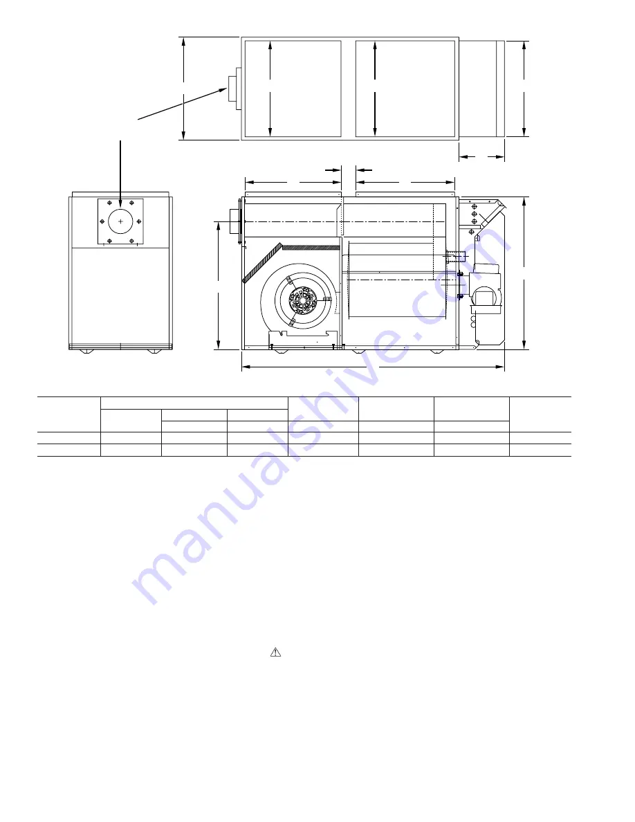
Fig. 2-Dimensional Drawing

Dimension (IN.)

UNIT

SIZE

UNIT DIMENSIONS

FLUE

HEIGHT

RETURN

OPENING

SUPPLY

OPENING

VENT

CONN

Width

Depth

Height

A

B

C

D

E

105-12

21-1/4

53-3/4

31-1/2

26-1/2

20

20

5

120-20

21-1/4

60-5/32

34-3/4

28-11/32

22

24

6

A98009

A

D

10"

E

3"

B

C

21 

1

4

20"

20"

20"

VENT 
CONN

2

Summary of Contents for 1-58CLA

Page 1: ...OF VAPOR OR WHEN THE COMBUSTION CHAMBER IS VERY HOT For use with grade 1 or 2 Fuel Oil Do not use Gasoline Crankcase Oil or any Oil containing Gasoline Failure to follow this warning could lead to sooting fire explosion and or severe bodily harm Never burn garbage or paper in the heating system and never leave rags paper or any flammable items around the unit Failure to follow this caution will re...

Page 2: ...ult in minor personal injury or product and property damage NOTE is used to highlight suggestions which will result in enhanced installation reliability or operation INTRODUCTION The model 58CLA Furnaces are available in 2 sizes Each size unit can be fired at 3 different rates by a simple nozzle change Unit 105 12 covers input ranges from 91 000 to 105 000 Btuh unit 120 20 covers input ranges from...

Page 3: ...amper is in full cool or heat position INSTALLATION Step 1 Air for Combustion and Ventilation Installation of this furnace in an area where it will receive contaminated combustion air must be avoided Such contami nation would include the following ammonia chlorine hydrogen sulfide halogenated hydrocarbons carbon tetra chloride cleaning solvents hydrochloric acid water soften ing chemicals and simi...

Page 4: ...hould be located about 6 in from top and bottom of enclosure at front of furnace See Table 3 NOTE In calculating free area consideration shall be given to blocking effect of louvers grilles or screens protecting openings Screens used shall not be smaller than 1 4 in mesh and shall be readily accessible for cleaning If free area through a design of louver or grille is known it shall be used in calc...

Page 5: ...efer to ANSI NFPA 211 Chimney Fireplaces Vents and Solid Fuel Burning Appliances and or CSA B139 Installation Code This furnace is certified for use with Type L vent maximum flue gas temperature 575 F Vent System Inspection Before furnace is installed it is highly recommended that any existing vent system be completely inspected For any chimney or vent this should include the following 1 Inspectio...

Page 6: ...al Code CSA C22 1 or subauthorities having jurisdiction Do not connect aluminum wire between disconnect switch and furnace Use only copper wire Failure to follow this caution will lead to intermittent electrical operation and or fire hazard The control system depends on correct polarity of power supply Connect HOT wire H and NEUTRAL wire N as shown in Fig 3 or 4 A separate line voltage supply MUST...

Page 7: ...required to determine thermal efficiency of fur nace 6 An oil filter should be installed as close to burner as possible with ALL oil burners and is essential on lower firing rate burners We recommend the use of a low pressure drop oil filter such as the General Filter Inc model 1A 25A or equivalent 7 The oil pressure regulator is factory set to give oil pressure of 130 psig for the model having 10...

Page 8: ...Fig 3 Wiring Diagram For 105 12 A03164 X04031 Rev A 8 ...

Page 9: ...Fig 4 Wiring Diagram For 120 20 A03165 X04032 Rev A 9 ...

Page 10: ...o keep this furnace in good operating condition and to maintain its warranty the furnace MUST be serviced on an annual basis This servicing includes a nozzle change a burner inspection a visual check of tube passages through flue outlet and cleanout ports and a visual inspection of combustion chamber when burner is removed Depending on above inspection service could also include a cleaning and vac...

Page 11: ...ed 8 After cleaning replace flue silencer flue collar and oil burner 9 Readjust burner for proper operation Step 4 Blower Removal To remove blower from furnace 1 Turn off all oil and electrical supplies upstream of furnace 2 Remove blower access door 3 Remove air filters 4 Remove blower retaining wing nuts 5 Slide blower on rails toward rear of unit 6 Reverse items 1 through 5 to reinstall blower ...

Page 12: ...31 58cla5si Manufacturer reserves the right to discontinue or change at any time specifications or designs without notice and without incurring obligations Book 1 4 Tab 6a 8a PC 101 Catalog No 535 80122 Printed in U S A Form 58CLA 5SI Pg 12 11 03 Replaces 58CLA 4SI ...

Reviews: