background image


INSTALLATION 
SELECTION OF MOUNTING POSITION


1)  The unit should be installed outdoors. 
2)  A place where air will not be stagnant. 
3)  A place where the exhausted air will not be sucked in for 

the second time. 

4)  Allow sufficient space for airflow clearance, wiring, 

refrigerant piping and servicing unit. See Fig. 2. 

5)  Avoid positioning unit in such a manner that water will 

pour directly onto the unit. 

6)  Do not install the unit near a source of heat, steam or 

flammable gas. 

7)  Ducting of the fan inlet or discharge is not permitted. 
 

UNIT MOUNTING 

1) 

MOUNTING ON GROUND

 – Mount on a solid, level 

concrete base. If conditions or local building codes 
require unit to be fastened to base, tie down bolts 
should be used and fastened through slots provided in 
unit’s mounting feet (Fig. 3). Do not install unit directly 
on ground. 

 
2) 

MOUNTING ON AND AGAINST THE WALL

 – the 

bracket is to be locally procured (Fig. 4). 


3) 

MOUNTING ON ROOF

 – Mount on a level platform or 

frame. When multiple unit are installed, the air outlet 
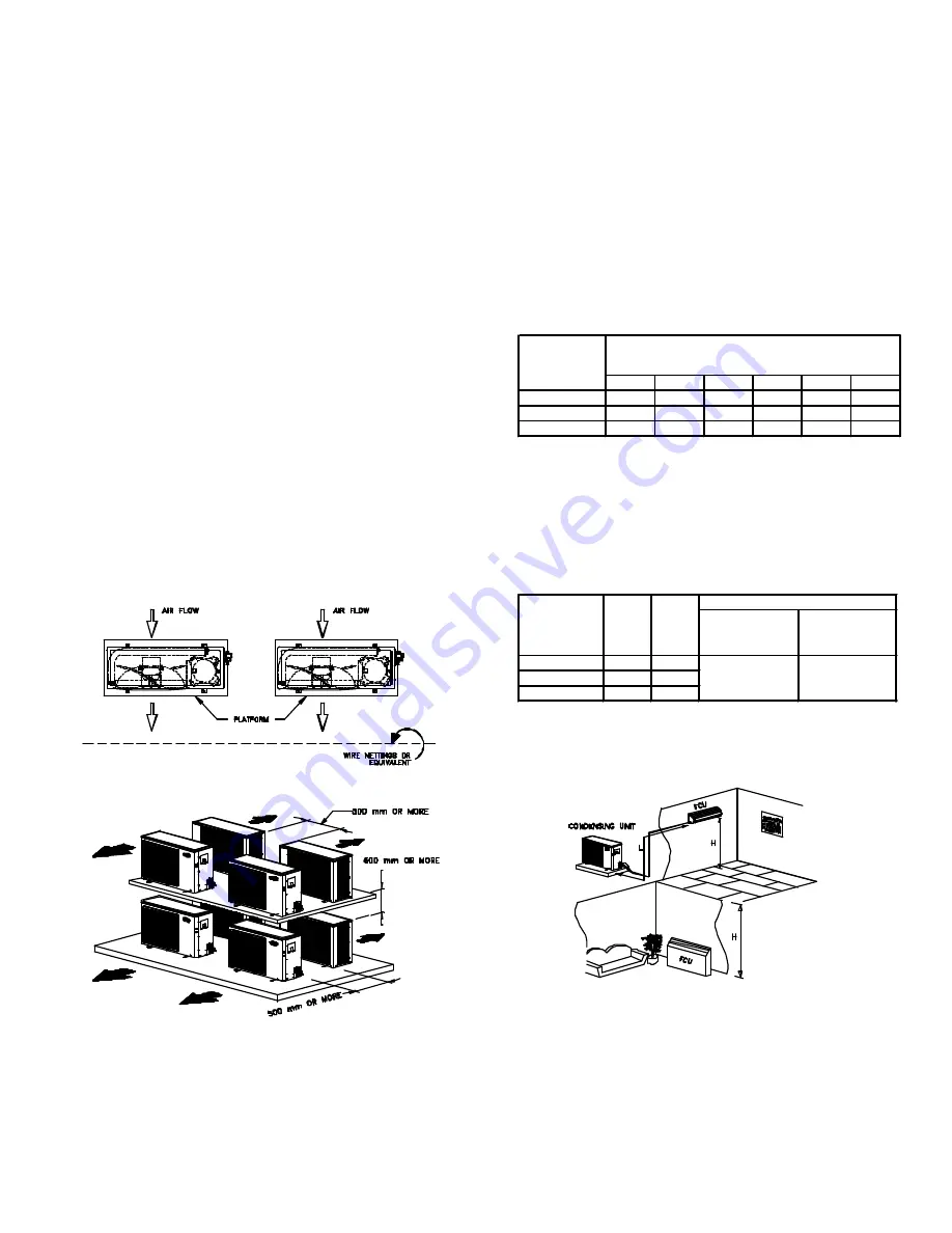
side should be opened as shown in Fig. 5. 


When installation base is used, secure the required spacing 
as per (Fig. 6). Fabricate the stand so that it will have 
sufficient strength. 


REFRIGERANT PIPING 

Size Refrigerant Lines. Consider length of piping required 
between unit and evaporator, amount of liquid lift and 
compressor oil return (Table 4). 


Run refrigerant tubes as directly as possible, avoiding 
unnecessary turns and bends. Condensing unit may be 
connected to evaporator sections using field-supplied 
tubing of refrigerant grade, correct size and condition. 
Suspend refrigerant tubes so they do not transmit 
vibration to structure. Also when passing refrigerant 
tubes through walls, seal opening so vibration is not 
transmitted to structure. Leave some slack in refrigerant 
tubes between structure and unit to absorb vibration. 
The longer the piping, the lower the cooling capacity of 
the unit. See table 3. 
 

TABLE 3 – REDUCTION IN CAPACITY VS    
                  INCREASE IN PIPE LENGTH 
 

MODEL

38ASB /

CCAR

5m

10m

15m

20m

25m

30m

240

0%

1.2%

2.0%

2.8%

3.5%

4.5%

360 / 036

0%

1.6%

2.6%

3.6%

4.6%

5.6%

600 / 060

0%

2.8%

4.8%

6.7%

8.7%

10.2%

PIPING LENGTH (ONE WAY)


As such the following are the operating limits. Refer to 
Table 4 and fig. 7. 
 

TABLE 4 – VERTICAL AND HORIZONTAL 
                   SEPARATION BETWEEN INDOOR 
                   AND OUTDOOR UNIT 
 

MODEL

MAX.

MAX.

38ASB /

HEIGHT LENGTH MAX. ALLOWABLE MAX. ALLOWABLE

CCARS024~060

H(m)

L(m)

PRESSURE DROP TEMPERATURE

(kPa)

LOSS (

0

C)

024

(20)15

25

360 / 036

(20)15

25

600 / 060

(25)15

30

LIQUID LINE

151

5

Note:


1) Values shown are for units operating at 7.2

0

C saturated suction 

              and 35

0

C entering air. 

          2) Values in ( ) indicate a case when the outdoor unit is located at  
              a lower height than the indoor unit. 


Do not bury section of line set underground. If any section is buried, 
refrigerant may migrate to cooled buried section during extended period of 
unit shutdown. This causes refrigerant slugging and possible compressor 
damage at start-up. 
 
If either refrigerant tubing or indoor coil is exposed to atmospheric 
conditions for longer than 5 minutes, it must be evacuated to 1000 microns 
to eliminate contamination and moisture in the system.


FIG. 5 ROOF MOUNTING 

FIG. 6 MINIMUM SPACING REQUIREMENT 

FIG. 7 MAXIMUM ALLOWABLE PIPING LENGTH 
           AND ELEVATION DIFFERENCE


4


Summary of Contents for 38ASB Series

Page 1: ... remove unit from the carton and take off protective covering If the unit has been damaged file claim with Transportation Company and notify Carrier immediately PROTECTION Protect unit from damage caused by job site debris Do not allow dust debris and water get into the unit These will damage unit s component and unit s performance will be affected 38ASB CCARS240 600 condensing units Fig 1 are shi...

Page 2: ...sed for 40KMC GKX 42GX AR 40LX Model used for SlimPack ASBFE600BA NEW MODEL NUMBER REMARKS 38ASB 3TR SERIES 38ASB240BA 38ASB360BA OLD MODEL NUMBER CCAR 5TR Single phase supply volatge CCARS024EA CCARS036EA CCARS060KA 2TR 38ASB036BA 38ASB060BA FIG 2 38ASB CCARS024 060 DIMENSIONAL DRAWING 2 ...

Page 3: ...ENSER COIL Rows Fins inch 2R 15 3 5R 15 Face Area m 2 0 379 CONNECTIONS Type Liquid mm inch Suction mm inch CONTROLS PRESSURES SWITCH High Cut Out psi SETTINGS Cut In psi Low Cut Out psi Cut In psi NOMINAL POWER SOURCE V Ph Hz ABSOLUTE MIN MAX VOLTAGE V 230V 3Ph 60Hz 19 05 3 4 15 88 5 8 Direct Drive 0 654 230V 1Ph 60Hz 230V 1Ph 60Hz 950 1 7 Flare 550 230V 3Ph 60Hz 230V 1Ph 60Hz Propeller 1 Permane...

Page 4: ... of refrigerant grade correct size and condition Suspend refrigerant tubes so they do not transmit vibration to structure Also when passing refrigerant tubes through walls seal opening so vibration is not transmitted to structure Leave some slack in refrigerant tubes between structure and unit to absorb vibration The longer the piping the lower the cooling capacity of the unit See table 3 TABLE 3 ...

Page 5: ...rce must agree with unit name plate rating 3 All service valves must be opened START SYTEM 1 Check that field disconnect is closed 2 Set room thermostat to below room temperature and unit compressor will start after 3 minutes delay o 3 Check back pressure when compressor runs Add charge to keep back pressure at approximately 448kPa 65 PSIG REFRIGERANT CHARGING IMPORTANT For accurate system perform...

Page 6: ...move dirt see Fig 10 Be sure to flush all dirt and debris from drain holes in base of unit Fan motor is water proof but it is more safe to cover or wrap motor shell with plastic sheet or plastic bag to prevent water from getting inside Clean coil semi annually or as required Fins are not continuous through coil sections Dirt and debris may pass between the row of fins and become trapped between th...

Page 7: ...PE740132 FIG 12 38ASB600DC WIRING DIAGRAM FIG 13 38ASB600DB WIRING DIAGRAM PE740133 NOTE FOR OTHER 38ASB WIRING DIAGRAM NOT SHOWN HERE PLEASE REQUEST COPIES FROM CCAC ENGINEERING DEPARTMENT 7 ...

Page 8: ... 16 1 17 8 19 4 20 6 22 2 23 3 25 15 5 3 9 5 6 6 7 8 3 10 11 7 13 3 15 16 7 18 3 19 4 21 1 22 2 23 9 18 3 3 3 5 8 7 2 8 9 10 6 11 7 13 3 15 16 7 18 3 20 21 1 22 8 21 1 3 9 5 6 7 2 8 9 10 6 11 7 13 3 15 16 7 18 3 20 21 7 23 9 3 3 5 6 7 8 3 10 11 7 13 3 15 6 17 2 18 9 20 6 26 7 2 8 4 4 6 7 8 3 10 11 7 13 9 15 6 17 2 19 4 29 4 4 4 6 1 8 3 10 6 12 2 14 4 16 7 18 3 32 2 2 8 5 7 2 8 9 11 1 13 3 15 17 2 ...

Page 9: ...FIG 14 SCHEMATIC SYSTEM WIRING DIAGRAM 38ASB240BA MATCHED WITH 42PGA026 38ASB240BA MATCHED WITH 42AR024 42GX024 38ASB360BA MATCHED WITH 42AR036 42GX040 9 ...

Page 10: ...38ASB240BA MATCHED WITH 40GKX KMC024 38ASB360BA MATCHED WITH 40GKX KMC036 FIG 15 SCHEMATIC SYSTEM WIRING DIAGRAM 38ASB360BA MATCHED WITH ASBFM360BA 10 ...

Page 11: ...FIG 16 SCHEMATIC SYSTEM WIRING DIAGRAM 38ASB360BA MATCHED WITH 40LX040 38ASB600DC MATCHED WITH 42AR 42GX060 11 ...

Page 12: ...38ASB600DC MATCHED WITH 40GKX KMC060 38ASB600DB MATCHED WITH 40LX060 12 ...

Page 13: ...38ASB600DC MATCHED WITH ASBFE600BA 13 ...

Page 14: ...ED OR CYLING COOLING OUTDOOR AIR RESTRICTED OR RECIRCULATING RESTRICTED DISCHARGE LINE OVERCHARGE OR NONCONDENSABLES IN SYSTEM LOW REFRIGERANT CHARGE LINE VOLTAGE TO HIGH OR LOW COMPRESSOR BEARINGS HIGH SUPERHEAT LOOSE LEAD AT FAN MOTOR MOTOR DEFECTIVE INCORRECT OUTDOORFANMOTOR CAPACITOR COMPRESSOR RUNS BUT INSUFFICIENT COOLING LOW SUCTION PRESSURE HIGH SUCTION LOW HEAD PRESSURE HIGH SUCTION LOW S...

Page 15: ...Tel No 63 2 850 1367 Fax No 63 2 809 9979 Website www carrier com ph Manufacturer reserve the right to discontinue or charge at any time specifications or designs without notice and without incurring obligations Form 38ASB CCARS024 060 1IOM Replaces NEW Concepcion Carrier Air conditioning Company Philippines 15 ...

Reviews: