background image

3

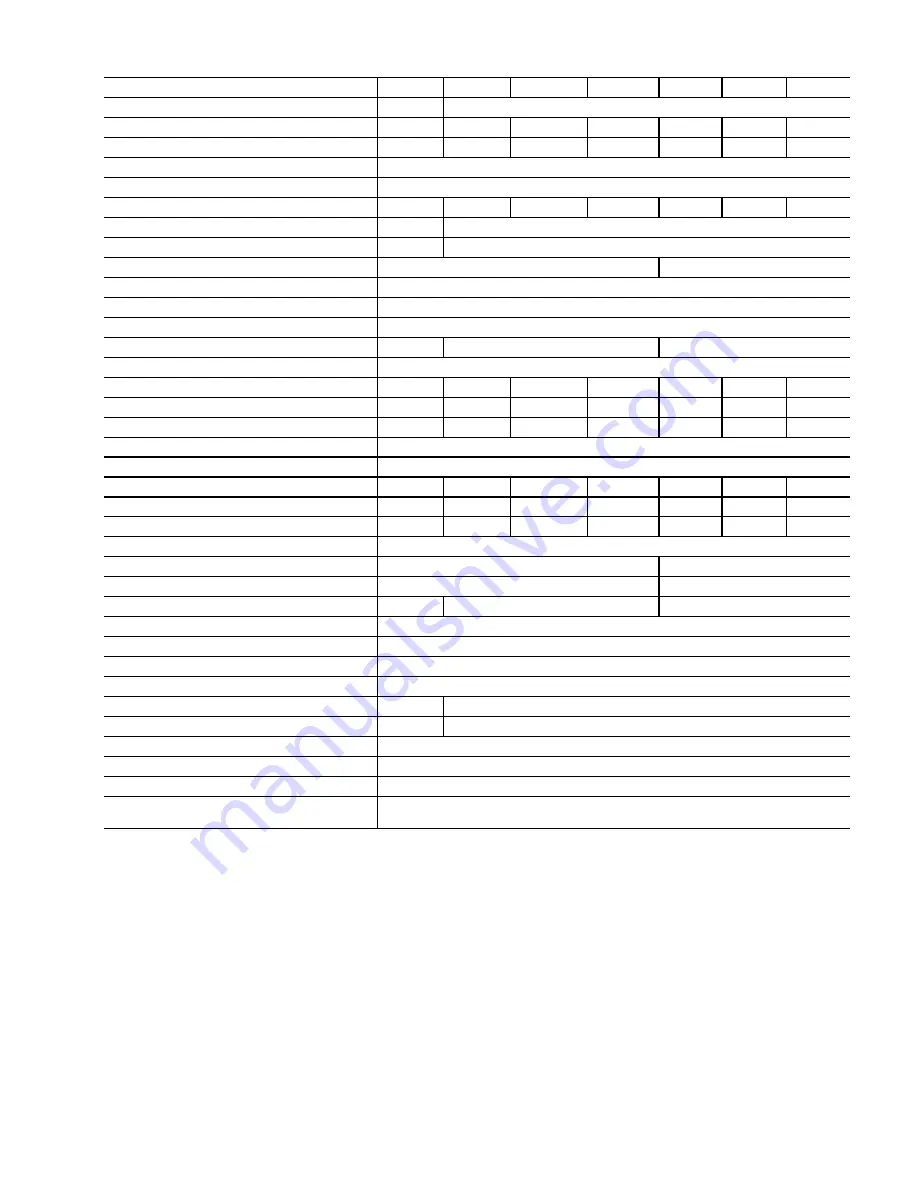
Table 2 —

 40VMV Physical Data

LEGEND

American Wire Gage
Electronic Expansion Valve

National Electric Code

*Gross weight includes packaging.

UNIT 40VMV

012

018

024

030

036

048

054

POWER SUPPLY (V-Ph-Hz)

208/230-1-60

COOLING CAPACITY (Btuh)

12,000

18,000

24,000

30,000

36,000

48,000

53,500

HEATING CAPACITY (Btuh)

13,500

21,000

27,000

34,000

40,000

54,000

60,000

INDOOR FAN MOTOR

Type

DC Motor

Input (W)

43

60

100

151

187

355

466

INDOOR COIL

Number of Rows

3

4

Fin Spacing (fins/in.)

16

17

Fin Type

Hydrophilic Aluminum

Tube Diameter, OD (in.)

0.276

Tube Type

Inner Groove

Number of Circuits

6

8

12

INDOOR AIRFLOW (cfm)

Low

320

420

560

   700

840

1120

1260

Medium

320

510

680

   850

1020

1360

1530

High

400

600

800

1000

1200

1600

1800

EXTERNAL STATIC PRESSURE (in. wg)

0.8

INDOOR UNIT NOISE LEVEL (dBA)

Low

34.5

34.4

37.9

44.4

39.3

43.8

47.9

Medium

34.5

37.1

42.3

48.4

44.1

48.5

52.6

High

37.6

41.6

46.2

52.2

46.9

53.0

57.1

UNIT

Unit Dimensions, W x H x D (in.)

19-5/8 x 46-1/2 x 20-5/8

22 x 54-1/2 x 24

Packing Dimensions, W x H x D (in.)

22-5/8 x 50-5/8 x 25-3/8

24-5/8 x 58-5/8 x 27-3/4

Net/Gross Weight (lb)*

119/143

123/147

163/189

REFRIGERANT TYPE

R-410A

THROTTLE

EEV

DESIGN PRESSURE (psig)

580/320

REFRIGERANT PIPING (in.)

Liquid Side, OD

1/4

3/8

Gas Side, OD

1/2

5/8

CONNECTING WIRING (AWG)

Power Wiring

Sized per NEC and local codes based on nameplate electrical data

Signal Wiring

2-core stranded shielded twisted pair cable 16-20 AWG

CONDENSATE DRAIN PIPE DIAMETER, OD 
(in.)

3/4


NPT

AWG

EEV

NEC

Summary of Contents for 40VMV012

Page 1: ...Canadian Electrical Code CSA Canadian Standards Association C22 1 Understand the signal words DANGER WARNING and CAUTION DANGER identifies the most serious hazards which will result in severe personal...

Page 2: ...at the steps outlined in this manual for initial inspection proper installation regular periodic maintenance and everyday operation of the unit be followed in detail This manual should be fully review...

Page 3: ...20 1260 Medium 320 510 680 850 1020 1360 1530 High 400 600 800 1000 1200 1600 1800 EXTERNAL STATIC PRESSURE in wg 0 8 INDOOR UNIT NOISE LEVEL dBA Low 34 5 34 4 37 9 44 4 39 3 43 8 47 9 Medium 34 5 37...

Page 4: ...mensions shown in inches 40VMV UNIT SIZE A B C D 012 030 46 1 2 19 5 8 18 21 5 8 036 054 54 1 2 22 19 1 2 24 RIGHT SIDE A FRONT B C D DRAIN PIPE LEFT SIDE AIR RETURN REFRIGERANT SIDE PIPE LIQUID REFRI...

Page 5: ...al dimensions such as pipe wire and duct connections requirements Refer to job drawings and product dimension drawings as required Instruct all trades in their parts of the installation Units must be...

Page 6: ...ould slope downward in the direction of condensate flow with a minimum gradient of 1 in per 100 inches Condensate piping should be installed in such a way that it does not block the front service pane...

Page 7: ...rect wiring or voltage is not covered by warranty Electric wiring must be sized to carry the full load amp draw of the motor starter and any other controls that are used with the unit See Table 4 for...

Page 8: ...ce N C 5 N 1 1 5 C Voltage range 0 24V AC DC Current range 0 1A FAN CTON HTON AUXH RED BLACK XS4 XP4 XS5 XP5 XS6 XP6 XT1 BLACK RED Y G CN27 CN3 CN18 CN31 CN54 CN4 CN15 CN19 CN8 CN21 CN12 CN26 CN14 CN2...

Page 9: ...e to buy communication wires from Carrier connect the indoor unit side of the communication wires using the connector provided with the accessories as shown in Fig 11 13 CAUTION Failure to follow thes...

Page 10: ...Fig 11 Connecting the Communication Cable to Indoor Unit to Outdoor Unit Using the Supplied Connector Connector in accessory kit Connector on indoor unit Communication cable in field 10...

Page 11: ...oor To Sub MDC To outdoor Indoor unit 1 L1 L2 L3 L3 L3 L3 L4 L5 L6 L7 L8 L9 L10 1 1 L Indoor unit 2 Indoor unit 3 Indoor unit 4 Indoor unit 5 Indoor unit 6 HA HB HA HB HA HB HA HB HA HB HA HB Touch sc...

Page 12: ...t Indoor unit 1 Indoor unit 2 Indoor unit 3 Indoor unit 4 Indoor unit 5 Indoor unit 6 P Q HA HB HA HB HA HB HA HB HA HB HA HB Network Resistor Maximum wiring length L1 L3 3937 ft 16 AWG 2 Core Strande...

Page 13: ...he power is restored MAINTENANCE CAUTION When servicing or repairing this unit use only factory approved service replacement parts Refer to the rating plate on the unit for complete unit model number...

Page 14: ...o an indoor unit Press ROOM TEMP and SWING simultaneously for 3 seconds If there is no address for this indoor unit the display shows FE 00 see Fig 16 otherwise the display shows the current address o...

Page 15: ...M Electronically Erasable Programmable Read only Memory EEV Electronic Expansion Valve MDC Multiport Distribution Controller ERROR CODE MODE STATUS NO ERROR Setting Temperature Starting Shutdown Stand...

Page 16: ...ignal wire close to electromagnetic source Distance signal wires from electromagnetic source PC board fault Replace PC board E2 E4 E5 Check Temperature Sensor Loose connection at port on PC board Tigh...

Page 17: ...1 START UP OFF Auto Addressing Mode Default ON Factory Test Mode POSITION 2 OFF Normal Mode Default ON Factory Self Checking Mode POSITION 3 NOT USED POSITION 4 INDOOR UNIT IDENTIFICATION OFF Standard...

Page 18: ...speed M speed 500 AIRFLOW cfm L speed 700 300 400 600 Upper Limit of ESP Fig B 40VMV018 Fan Curves Fig A 40VMV012 Fan Curves 0 00 0 20 0 40 0 60 0 80 1 00 EXTERNAL STATIC PRESSURE in wg H speed 500 A...

Page 19: ...0VMV048 Fan Curves 0 00 0 20 0 40 0 60 0 80 1 00 1000 1200 1400 1600 1800 2000 EXTERNAL STATIC PRESSURE in wg H speed M speed Upper Limit of ESP L speed AIRFLOW cfm Fig G 40VMV054 Fan Curves 0 00 0 20...

Page 20: ...ight to discontinue or change at any time specifications or designs without notice and without incurring obligations Catalog No 16 40VMV001 01 Printed in U S A Form 40VM 2SI Pg 20 2 17 Replaces 40VM 1...

Reviews: