13
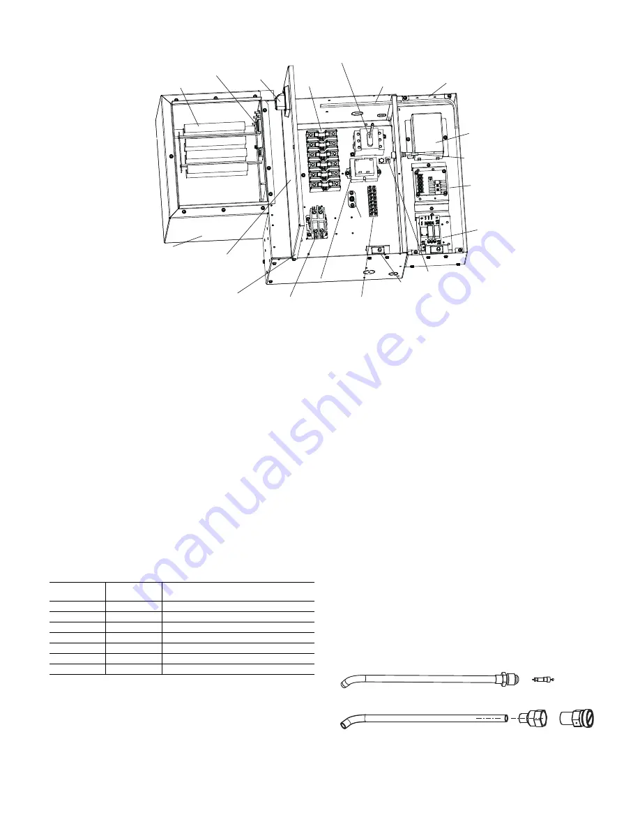
Fig. 20 — Control Box Layout
Step 6 — Make Final Preparations
1. Power unit(s) off (open unit electrical disconnect) and
install lockout tags on all power supplies to the unit.
2. Install field-supplied thermostats and perform all other
final wiring needed. Ensure all electrical connections are
secure.
3. Perform final visual inspection. All equipment, ductwork,
and piping should be inspected to verify all systems are
complete and properly installed and mounted, and that no
debris or foreign articles are left in the unit(s). Clean dirt,
dust, and other construction debris from unit interior.
Assess fan wheel and housing and clean if necessary.
4. Verify drain line is properly and securely positioned and that
the line is clear. Pour water into drain to verify operation.
5. Rotate fan wheel by hand to be sure it is free and does not
rub housing.
6. Install the filter into the filter frame. If field-supplied fil-
ters are used, verify filter size (see Table 4).
Table 4 — Filter Sizes
7. Ensure all panels and filters are installed before checking
fan operation. Turn on power to the unit.
8. Inspect the fan and motor operation.
START-UP
Before beginning any start-up operation, the start-up personnel
shall familiarize themselves with the unit, options and accesso-
ries, and control sequence to understand the proper system op-
eration. All personnel shall have a good working knowledge of
general start-up procedures and have the appropriate start-up
and balancing guides available for consultation.
The building must be completely finished including doors,
windows, and insulation. All internal walls and doors should
be installed. In some cases, the interior decorations and furni-
ture may influence overall system performance. The entire
building should be as complete as possible before beginning
any system balancing.
Cooling/Heating System
Prior to the water system start-up and balancing, flush the
chilled/hot water systems to clean out dirt and debris which
may have collected in the piping during construction. During
this procedure, all unit service valves must be in the closed po-
sition to prevent foreign matter from entering the unit and clog-
ging the valves and metering devices. Strainers shall be in-
stalled in the piping mains to prevent such material from enter-
ing units during normal operation.
During system filling, air venting from the unit is accomplished
by the use of the standard, manual air vent fitting, or the option-
al, automatic air vent fitting installed on the coil (Fig. 21). Man-
ual air vents are basic Schrader valves that could be accessed
from the coil side of the unit and are located between the coil
header and end sheet. To vent the air from the coil, depress the
valve until the air has vented the coil. When water begins to es-
cape through the valve, release the valve.
Automatic air vents may be unscrewed one turn counterclock-
wise to speed initial venting, but should be screwed in for auto-
matic venting after start-up operations.
Fig. 21 — Air Vents
Motor
Control
Board
Equipment
Ground
Terminal
Terminal Strip
Wiring Diagram
(inside the door)
Serial Plate
Wrapper
Contactors
Transformer
Electric Heater
Limit Switch
Knob
Heater Fuses
Auxillary Control Box
(supplied when ordered
with
3-speed
controls
and/or service light)
Service Light
Strip
Battery
Charger
Service Light
Battery
Door Switch
Bonded
Ground
24V Control
Fuse
Disconnect Switch
Above is the example of Control box for Size 20 unit with electric heat, disconnect switch and service light.
42DH UNIT
SIZE
FILTER
QUANTITY
NOMINAL FILTER SIZES —
in. (mm)
06
1
16
1
/
2
x 24 (419 x 610)
08
1
16
1
/
2
x 24 (419 x 610)
10
1
18
1
/
4
x 33 (464 x 838)
12
1
18
1
/
4
x 33 (464 x 838)
16
2
18
1
/
4
x 21
1
/
2
(464 x 546)
20/22
2
20
1
/
2
x 22 (521 x 559)
30
2
29 x 22 (737 x 559)
Manual Air Vent
Automatic Air Vent


