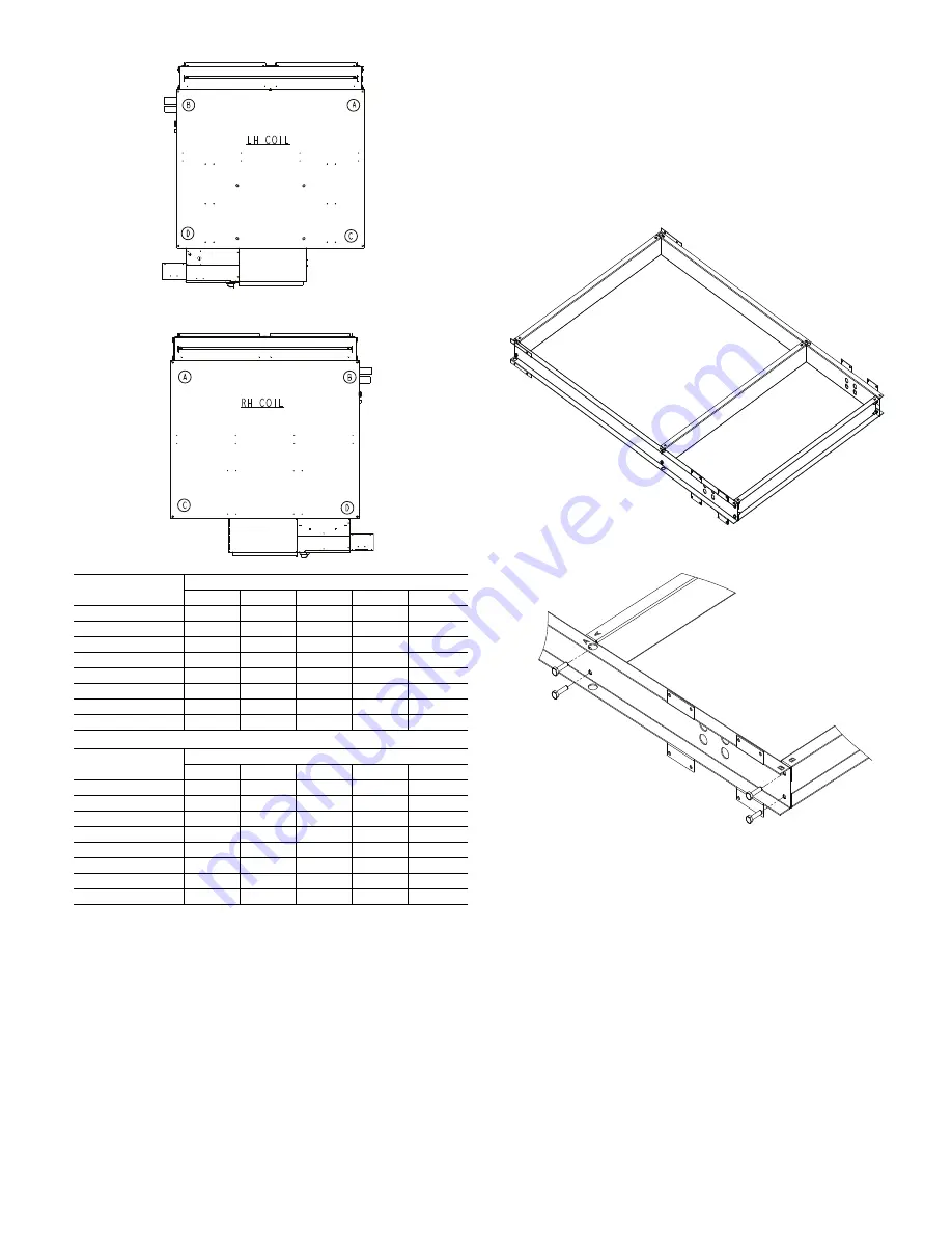
5
Fig. 5 — Weight Distribution Calculations
Step 2 — Install Mixing Box
1. Mixing boxes are pre-assembled from the factory for ease
of installation. A linkage kit consisting of two crank arms,
2 swivels, and either a 25-in. (sizes 06-16) or a 34-in.
(sizes 20-30) length of
5
/
16
in. rod is provided for field
installation of an actuator.
2. Assemble the base rails (provided with mixing box, see
Fig. 6). All hardware required for assembly is included
and the base rails are letter coded for ease of assembly (as
shown in Fig. 7).
Fig. 6 — Base Rails
Fig. 7 — Letter Coding on Base Rail Parts
3. Place unit on the base rails making sure that the unit is
mounted flush to the outer edge of the end base rail at the
aligning unit mounting holes (as shown in Fig. 8). It may
be necessary to remove factory installed sheet metal
screws to enable access to all mounting holes and to
ensure proper fit. Do not remove screws unless necessary.
Secure unit to base rail using No. 8 x
1
/
2
-in. fasteners at the
locations shown in Fig. 7 and 8, two per side.
42DH UNIT
NO ELECTRIC HEAT (lb)
A
B
C
D
Total
06
42
46
36
47
171
08
41
47
38
45
171
10
51
53
49
63
217
12
50
52
51
64
217
16
65
70
64
75
274
20
78
90
77
95
340
22
83
108
80
99
367
30
103
113
97
117
430
42DH UNIT
WITH ELECTRIC HEAT (lb)
A
B
C
D
Total
06
42
58
36
66
202
08
41
58
36
67
202
10
51
60
56
83
250
12
50
58
57
85
250
16
70
69
66
104
309
20
81
96
77
107
378
22
86
111
81
111
389
30
104
120
96
149
469


