background image

32

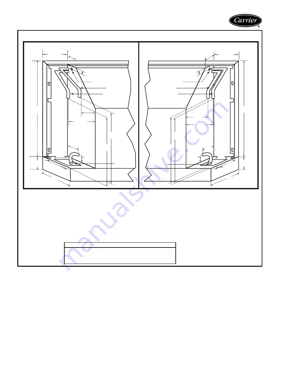
Typical piping and wiring

1.25

(32)

1.5

(38)

7.13

(181)

3.5

(89)

3.16 (80)

2 (51)

1 (25)

Power Supply In

Water In

Power Supply In

Water In

Condensate

Drain

Condensate

Drain

Water Out

Water Out

3.5 (89)

9.5

(241)

2 (51)

1.5

(38)

7.13

(181)

1.5

(38)

21

(533)

3.5

(89)

1 (25)

3.5 (89)

3

(76)

21

(533)

3

(76)

9.5

(241)

13

(330)

13

(330)

3.5 (89)

5.5 (140)

5.5  (140)

3.5

(89)

1

(25)

13

(330)

13

(330)

L E F T   H A N D

R I G H T   H A N D

Subbase available only on bottom return units

No condensate trap required

.

Electrical wiring and water piping may enter the cabinet either:

1. From below, passing up through the 7

1

/

8

-in. (181) x 3

1

/

2

-in. (89) opening in the subbase.

2. From behind, passing through the 4

1

/

2

-in. (114) wide opening in the rear cabinet.

3. Be sure adequate room is given for any accessories like valves, disconnect switches, etc.
4. All measurements in inches. Measurements in parentheses are in millimeters.

Piping Connections Available

Female Pipe Thread
Sweat Copper Pipe (shown above)
Motorized Water Valve (see separate submittal page)
Male Pipe Thread

STANDARD UNIT

Summary of Contents for 50KQA

Page 1: ...tors and control valves for easy installation Flexible and reliable controls accommodate all systems Features Benefits Carrier s Aquazone console water source heat pumps are a flexible attractive alternative for all finished interior space under window style installations Operating efficiency Carrier Aquazone water source heat pumps WSHP are designed for quali ty and performance excellence over th...

Page 2: ...ate line Compact cabinet design dimen sions are 10 in deep 48 in wide and 24 in tall with 3 in subbase For flexibility the controls can be mounted on the top right or left side Additionally the sloped top design discourages the use of the unit as a shelf or coffee holder preventing air blockage and any spills from damaging the unit No fuss maintenance and serviceability Regular maintenance or serv...

Page 3: ...es of emergency electric heat Service test mode with diagnostic LED light emitting diode Test mode allows service personnel to check the operation of the WSHP and control system efficiently Upon enter ing test mode time delays speed up and the Status LED flashes a code indicating the last fault This mode provides easy fault diagnosis based on the fault code the status LED flashes Carrier provided ...

Page 4: ...ch 15A Fuse F Disconnect Switch Non Fused H 20A Plug Cord Receptacle Disconnect Switch 15A Fuse K 20A Plug Cord Receptacle Disconnect Switch No Fuse Revision Code 0 Current Revision Water Circuit Options Controls A Manual Changeover with Complete C Microprocessor Board B Manual Changeover with Deluxe D Microprocessor Board C Automatic Changeover with Complete C Microprocessor Board D Automatic Cha...

Page 5: ...2 x 1 8 7 x 291 2 x 1 8 7 x 291 2 x 1 8 7 x 291 2 x 1 8 UNIT WEIGHT lb Shipping Operating 158 151 162 154 172 164 178 168 183 174 REF TO AIR HEAT EXCHANGER Face Area sq ft No of Rows Deep Copper Tube Size O D in No of Fins in 1 44 2 3 8 13 1 44 2 3 8 13 1 44 3 3 8 13 1 81 3 3 8 13 1 81 3 3 8 13 REFRIG CHARGE R 22 CKT oz No of Circuits 16 1 16 1 21 1 23 1 22 1 UNIT CABINET W STAND SUBBASE W x H x D...

Page 6: ...th dual stage units units with 2 compressors and 2 D controls or in master slave applications Boilerless electric heat control system Allows automatic changeover to electric heat at low loop water temperature Intelligent reversing valve operation Minimizes reversing valve operation for extended life and quiet operation Thermostat type select Y O or Y W Provides ability to work and select heat pump...

Page 7: ...o control 10 or 18 zones of WSHP units Panel can be ordered to control variable frequency cool ing tower fan operation System pumping operation can be configured for start stop lead lag or variable frequency pump operation Direct Digital Control compatible using the Carrier Comfort Network CCN and WSHP units utilizing PremierLink CCN controllers Fire rated hoses are 2 ft long and have a fixed MPT ...

Page 8: ...COMMUNICATING CONTROL COOL HEAT AUTO R 5 DAY PROGRAMMABLE NON PROGRAMMABLE AUTO Pm COOL HEAT Carrier CARRIER AQUAZONE THERMOSTATS FOR USE WITH REMOTE THERMOSTAT UNITS 7 DAY PROGRAMMABLE LIGHT ACTIVATED PROGRAMMABLE 7 DAY PROGRAMMABLE FLUSH MOUNT ...

Page 9: ...610 16 406 FRONT VIEW DAMPER OPENING 48 1219 1 63 41 11 75 298 9 75 248 0 81 21 21 533 3 76 REAR VIEW Control Access Door AIR INLETAREA Air Inlet Discharge Air 1 5 38 3 5 89 0 75 19 R H Pipe Electric Area REAR ACCESS 1 25 1 25 4 5 114 20 508 10 254 8 203 48 1219 48 1219 9 5 241 Optional 5 in 127 sub base will increase damper opening to 3 63 in 92 high and increase overall unit height by 2 in 51 ...

Page 10: ...ischarge Air 89 10 254 48 1219 48 1219 1 5 38 3 5 9 5 241 1 25 4 5 114 20 21 533 3 76 1 25 REAR ACCESS 508 L H Pipe Electric Area 8 203 0 75 19 NOTE All measurements in inches Measurements in parentheses are in millimeters 50KQA KQD BOTTOM RETURN CABINET DIMENSIONS LEFT HAND PIPING Optional 5 in 127 subbase will increase damper opening to 3 63 in 92 high and increase overall unit height by 2 in 51...

Page 11: ...CTRIC AREA 0 75 19 3 5 89 30 10 254 1 5 38 Filter 48 1219 21 533 FRONT VIEW Control Access Door 5 127 16 406 Air Discharge Air Inlet 21 533 48 1219 REAR VIEW REAR ACCESS 1 25 4 5 114 1 25 20 508 NOTE All measurements in inches Measurements in parentheses are in millimeters 50KQA KQD FRONT RETURN CABINET DIMENSIONS RIGHT HAND PIPING ...

Page 12: ...OFF PLATE ON BOTTOM OF CHASSIS 3 5 89 30 10 254 1 5 38 Filter 48 1219 21 533 FRONT VIEW Control Access Door 1 5 38 12 5 318 Air Inlet Air Discharge 21 533 48 1219 REAR VIEW 1 25 1 25 4 5 114 REAR ACCESS 20 508 NOTE All measurements in inches Measurements in parentheses are in millimeters 50KQA KQD FRONT RETURN CABINET DIMENSIONS LEFT HAND PIPING ...

Page 13: ... LH 30 3 375 86 2 51 4 102 5 127 16 406 1 5 38 9 5 241 1 25 CONDENSATE RELIEF FRONT VIEW RH SIDE VIEW RH POWER SUPPLY IN 13 330 1 25 0 75 19 2 51 3 5 89 2 51 BLOWER DECK BLOWER ACCESS PANEL CONTROL BOX COMPRESSOR ACCESS PANEL 41 1041 20 5 521 WATER OUT WATER IN WATER IN WATER OUT 0 75 19 0 75 19 0 75 19 NOTE All measurements in inches Measurements in parentheses are in millimeters 50KQA KQD CHASSI...

Page 14: ... bulb and wet bulb using the Corrections Factor tables found in this book Using the following formulas to determine the cor rection factors of dry bulb and wet bulb a Corrected Total Cooling tabulated total cooling x wet bulb correction x airflow correction b Corrected Sensible Cooling tabulated sensible cooling x wet dry bulb correction x airflow correction V Determine entering air and airflow co...

Page 15: ... 412 Power Input in watts fan power correction in watts pump power correction in watts Watts Watts NOTE Do not divide ISO Heating Capacity by 3 412 to obtain Btuh Watts Refer to English to SI conversion table in this book b Identify the design conditions corrected for air and water conditions Airflow Cfm 325 Cfm Water Flow Based upon 12 F rise in temp 3 0 GPM External Static Pressure 0 0 in wg non...

Page 16: ... 6 3 0 71 0 42 10 3 6 7 0 58 4 8 5 0 6 2 7 3 50 1 5 8 4 6 2 0 74 0 44 9 9 7 4 0 61 5 4 1 8 2 2 2 6 1 9 8 5 6 3 0 74 0 44 10 0 7 6 0 60 5 5 2 3 3 0 3 6 2 5 8 6 6 3 0 73 0 43 10 0 7 7 0 60 5 7 5 0 6 2 7 3 60 1 5 8 1 6 1 0 75 0 47 9 7 8 4 0 62 6 3 1 8 2 2 2 6 1 9 8 2 6 1 0 75 0 46 9 8 8 6 0 61 6 5 2 3 3 0 3 6 2 5 8 2 6 1 0 75 0 46 9 8 8 8 0 63 6 6 5 0 6 2 7 3 70 1 5 7 8 6 0 0 77 0 51 9 5 9 4 0 64 7 2...

Page 17: ... 44 12 4 8 2 0 67 6 0 7 2 8 9 10 5 50 1 7 10 4 7 6 0 73 0 51 12 2 9 0 0 70 6 7 2 3 2 8 3 4 2 3 10 5 7 6 0 73 0 49 12 2 9 3 0 70 6 9 4 3 5 3 6 3 3 0 10 5 7 7 0 73 0 48 12 2 9 4 0 71 7 0 7 2 8 9 10 5 60 1 7 10 0 7 4 0 74 0 56 11 9 10 2 0 73 7 7 2 3 2 8 3 4 2 3 10 1 7 5 0 74 0 55 12 0 10 4 0 73 7 9 4 3 5 3 6 3 3 0 10 2 7 5 0 74 0 54 12 0 10 6 0 74 8 1 7 2 8 9 10 5 70 1 7 9 7 7 3 0 75 0 63 11 8 11 3 0...

Page 18: ...0 2 3 13 3 7 4 0 55 0 74 15 9 10 7 0 89 7 6 5 5 6 5 7 5 3 0 13 5 7 4 0 55 0 72 15 9 10 9 0 89 7 9 9 7 11 4 13 0 4 0 13 6 7 5 0 55 0 70 16 0 11 1 0 90 8 0 16 6 19 6 22 5 60 2 3 12 9 7 4 0 58 0 82 15 7 12 1 0 93 8 9 5 5 6 5 7 5 3 0 13 0 7 5 0 57 0 79 15 7 12 3 0 95 9 1 9 7 11 4 13 0 4 0 13 1 7 5 0 57 0 78 15 8 12 5 0 97 9 2 16 6 19 6 22 5 70 2 3 12 4 7 4 0 60 0 89 15 5 13 5 0 99 10 1 5 5 6 5 7 5 3 0...

Page 19: ...13 8 1 5 0 9 5 13 9 50 2 7 16 1 10 6 0 66 0 92 19 2 13 2 1 18 9 2 1 5 2 9 4 2 3 7 16 3 10 7 0 66 0 87 19 3 13 6 1 17 9 6 3 0 5 6 8 1 4 9 16 5 10 8 0 66 0 84 19 4 13 8 1 19 9 8 5 0 9 5 13 9 60 2 7 15 6 10 4 0 67 0 95 18 9 15 1 1 23 10 9 1 5 2 9 4 2 3 7 15 8 10 5 0 66 0 91 18 9 15 5 1 26 11 2 3 0 5 6 8 1 4 9 16 0 10 6 0 66 0 89 19 0 15 6 1 23 11 4 5 0 9 5 13 9 70 2 7 15 1 10 2 0 67 1 08 18 8 17 0 1 ...

Page 20: ...3 5 18 9 11 7 0 62 1 09 22 6 17 0 1 46 12 0 2 6 4 9 7 1 4 5 19 0 11 8 0 62 1 05 22 6 17 4 1 50 12 3 4 2 8 0 11 7 6 0 19 2 11 9 0 62 1 03 22 7 17 7 1 53 12 5 8 3 15 1 21 6 60 3 5 18 3 11 4 0 63 1 19 22 3 19 1 1 56 13 8 2 6 4 9 7 1 4 5 18 4 11 5 0 62 1 16 22 4 19 6 1 59 14 1 4 2 8 0 11 7 6 0 18 6 11 6 0 62 1 13 22 5 20 0 1 63 14 4 8 3 15 1 21 6 70 3 5 17 6 11 2 0 64 1 30 22 1 21 3 1 65 15 7 2 6 4 9 ...

Page 21: ...0 856 73 0 961 0 930 0 924 0 957 0 977 1 088 0 885 80 0 971 0 947 0 943 0 968 0 982 1 066 0 914 87 0 980 0 964 0 961 0 978 0 988 1 045 0 941 92 0 990 0 982 0 981 0 989 0 994 1 023 0 971 100 1 000 1 000 1 000 1 000 1 000 1 000 1 000 107 1 011 1 019 1 021 1 012 1 006 0 976 1 031 113 1 020 1 035 1 038 1 022 1 012 0 956 1 058 COOLING CORRECTIONS HEATING CORRECTIONS Entering Air Wet Bulb F Total Coolin...

Page 22: ...rface The number of coils required depends on system load and design This application requires minimum piping and excavation Open loop system Use this system where ground water is plentiful In this application ground water is pumped through supply piping from the well to the build ing The water is then pumped back into the ground through a discharge well as it leaves the building An addi tional he...

Page 23: ...water loop applications Aqua zone WSHP units use copper water to refrigerant heat exchanger Units can also be equipped with a Cupronickel heat exchanger for applications where water is outside the copper heat exchanger s standard contaminant limits WATER QUALITY GUIDELINES If the concentration of these corrosives exceeds the maximum allow able level then the potential for serious corrosion problem...

Page 24: ...S 1 Minimum Air and Water conditions can only be used at ARI flow rates 2 Only one maximum or minimum value may be used with 50KQA units all other parameters must be at normal conditions The 50KQA units may have up two values at maximum or minimum with all other parameters at normal conditions Solenoid valves In applications using variable flow pumping solenoid valves can be factory installed and ...

Page 25: ...0 1 60 197 254 3 8 20 0 0 33 4 8 6 0 15 265 1 60 239 292 3 3 18 6 0 35 3 7 4 5 15 012 115 1 60 104 126 9 7 54 0 1 28 11 5 14 0 20 208 230 1 60 197 254 4 8 26 3 0 52 5 4 6 6 15 265 1 60 239 292 4 2 28 0 0 43 4 8 5 9 15 015 208 230 1 60 197 254 6 4 38 0 0 52 7 5 9 3 15 265 1 60 239 292 5 4 32 0 0 43 5 9 7 3 15 019 208 230 1 60 197 254 7 6 45 0 1 10 9 4 11 5 15 265 1 60 239 292 6 3 32 0 0 83 7 2 8 8 ...

Page 26: ...EAT X O O X X O O X X BLOWER MOTOR WIRING UNIT SIZE POLE A POLE B 007 5 3 009 5 3 012 5 4 015 4 3 019 4 3 AL Alarm Relay Contacts BM Blower Motor BR Blower Relay Cap Capacitor CO Condensate Overflow CR Compressor Relay DM Damper Motor FP1 Sensor Water Coil Freeze Protection FP2 Sensor Air Coil Freeze Protection HP High Pressure Switch JW1 Jumper Wire for Alarm LOC Loss of Charge Pressure Switch PB...

Page 27: ...Trace Optional Low Voltage Wiring Relay Contactor Coil Solenoid Coil Thermistor Ground Mate N Lock NOTES 1 Compressor and Blower Motor thermally protected internally 2 All wiring to the unit must comply with NEC and local codes 3 Transformer is wired to 115V WHT lead for 115 1 60 units 265V BRN Lead for 265 1 60 units or 208V RED Lead for 208 1 60 For 230 1 60 switch RED and ORG Leads at L1 and in...

Page 28: ...o tected internally 2 All wiring to the unit must comply with NEC and local codes 3 Transformer is wired to 115V WHT lead for 115 1 60 units 265V BRN Lead for 265 1 60 units or 208V RED Lead for 208 1 60 For 230 1 60 switch RED and ORG Leads at L1 and insulate RED lead Transformer is energy limiting or may have circuit breaker 4 FP1 Thermistor provides freeze protection for WATER When using ANTI F...

Page 29: ...5 3 009 5 3 012 5 4 015 4 3 019 4 3 PUSH BUTTON SWITCH ATTRIBUTES X CLOSED O OPEN TERMINALS 1 2 3 4 5 6 7 8 1A 1B 2A 3A 4A 5A 6A 7A 8A STOP X O O O O O O O O FAN ONLY X O O O O X O O O LOW FAN X O O X X O X O O HIGH FAN X O O X X O O X X Field Line Voltage Wiring Field Low Voltage Wiring Printed Circuit Trace Optional Low Voltage Wiring Relay Contactor Coil Solenoid Coil Thermistor Ground Mate N L...

Page 30: ...mpressor and Blower Motor thermally pro tected internally 2 All wiring to the unit must comply with NEC and local codes 3 Transformer is wired to 115V WHT lead for 115 1 60 units 265V BRN Lead for 265 1 60 units or 208V RED Lead for 208 1 60 For 230 1 60 switch RED and ORG Leads at L1 and insulate RED lead Transformer is energy limiting or may have circuit breaker 4 FP1 Thermistor provides freeze ...

Page 31: ... RELAY FAULT STATUS R RV G TEST Y Microprocessor D NO COM NO 1 FP2 CO P7 12 RV 9 10 8 4 FP1 6 7 5 LOC HP 3 2 NC SPEED RELAY FAN RELAY JW4 NOTES 1 Compressor and Blower Motor thermally protected internally 2 All wiring to the unit must comply with NEC and local codes 3 Transformer is wired to 115V WHT lead for 115 1 60 units 265V BRN Lead for 265 1 60 units or 208V RED Lead for 208 1 60 For 230 1 6...

Page 32: ... bottom return units No condensate trap required Electrical wiring and water piping may enter the cabinet either 1 From below passing up through the 71 8 in 181 x 31 2 in 89 opening in the subbase 2 From behind passing through the 41 2 in 114 wide opening in the rear cabinet 3 Be sure adequate room is given for any accessories like valves disconnect switches etc 4 All measurements in inches Measur...

Page 33: ... 3 5 89 3 5 89 3 5 89 2 51 WITH MOTORIZED SHUT OFF VALVE Subbase available only on bottom return units No condensate trap required Electrical wiring and water piping may enter the cabinet either 1 From below passing up through the 71 8 in 181 x 31 2 in 89 opening in the subbase 2 From behind passing through the 41 2 in 114 wide opening in the rear cabinet 3 All measurements in inches Measurements ...

Page 34: ...330 13 330 13 330 5 5 140 2 51 1 5 38 9 5 241 3 76 7 178 7 5 191 21 533 4 25 108 Fuses Power Supply In 1 25 32 1 25 3 5 89 L E F T H A N D R I G H T H A N D Subbase available only on bottom return units No condensate trap required Electrical wiring and water piping may enter the cabinet either 1 From below passing up through the 71 8 in 181 x 31 2 in 89 opening in the subbase 2 From behind passing...

Page 35: ...The cabinet shall be powder painted C Fan and Motor Assembly The fan motors shall be multi speed permanently lubricated PSC permanent split capacitor type with thermal overload protection To facilitate field service all units shall have a slide out fan deck and quick electrical disconnect D Refrigerant Components 1 Units shall have a sealed refrigerant circuit includ ing a hermetic compressor a re...

Page 36: ...Cool Hi Heat Lo Heat Unit mounted thermostats shall have a remote sensor for sensing the return air temperature 5 The optional Deluxe D electronic control shall have all the features of the Complete C control with the following additional features a 75 VA transformer b A removable thermostat connector c Random start on return from night setback d Minimized reversing value operation for extended li...

Page 37: ...by the remote thermostat G Special Features 1 Aquazone Thermostat Controls for use with remote thermostat units a Programmable multi stage thermostat with 7 day clock holiday scheduling large backlit display and remote sensor capability b Programmable 7 Day Light Activated Ther mostat offers occupied comfort settings with lights on unoccupied energy savings with lights off c Programmable 7 Day Flu...

Page 38: ......

Page 39: ......

Page 40: ...at any time specifications or designs without notice and without incurring obligations New Pg 40 Catalog No 525 00049 Printed in U S A PC 111 Form 50KQ 6PD Replaces 50KQ 5PD Book 1 4 Tab 5a 5a Carrier Corporation Syracuse New York 13221 5 03 Book 1 Tab 1IP4a ...

Reviews: