background image

19

A190368

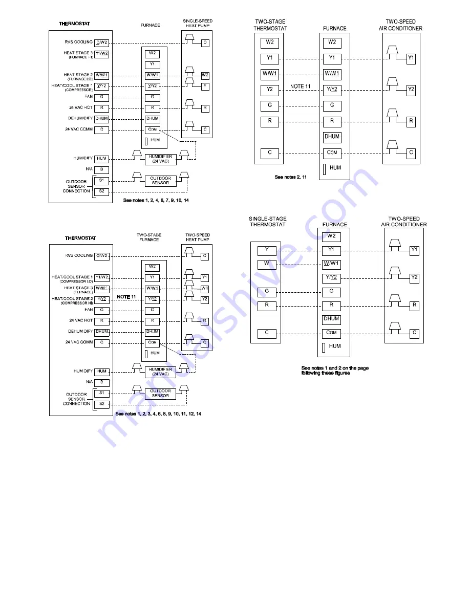
Fig. 27 -- 1--Speed Variable Furnace with Single--Speed Heat

Pump (Dual Fuel)

A190370

Fig. 28 -- 1--Speed Variable Furnace with Two--Speed Heat

Pump (Dual Fuel)

A190371

Fig. 29 -- Two--Stage Thermostat with 1--Speed Variable Fur-

nace and Two--Speed Air Conditioner

A190173

Fig. 30 -- Single--Stage Thermostat with 1--Speed Variable

Furnace and Two--Speed Air Conditioner

NOTES FOR FIGURES 25 -- 30

1. Heat pump MUST have a high pressure switch for dual fuel applications.

2. Refer to outdoor equipment Installation Instructions for additional information and setup procedure.

3. If the heat pump date code is 1501E or earlier, select the “ZONE” position on the two--speed heat pump control. Heat pumps having date codes 1601E and

later do not have or require a “ZONE” selection.

4. Outdoor Air Temperature Sensor must be attached in all dual fuel applications.

5. Dip switch No. 1 on Thermidistat should be set in OFF position for air conditioner installations. This is factory default.

6. Dip switch No. 1 on Thermidistat should be set in ON position for heat pump installations.

7. Dip switch No. 2 on Thermidistat should be set in OFF position for single--speed compressor operation. This is factory default.

8. Dip switch No. 2 on Thermidistat should be set in ON position for two--speed compressor operation.

9. Configuration Option No. 10 “Dual Fuel Selection” must be turned ON in all dual fuel applications.

10. NO connection should be made to the furnace HUM terminal when using a Thermidistat.

11. Optional connection: If wire is connected, ACRDJ jumper on furnace control should be removed to allow Thermidistat/Thermostat to control outdoor unit

staging.

12. Furnace must control its own stage heating operation via furnace control algorithm.

13. The RVS Sensing terminal “L” should not be connected. This is internally used to sense defrost operation.

14. DO NOT SELECT the “FURNACE INTERFACE” or “BALANCE POINT” option on the two--speed heat pump control board. This is controlled internally

by the Thermidistat/Dual Fuel Thermostat.

15. Dip switch D on Dual Fuel Thermostat should be set in OFF position for single--speed compressor operation. This is factory default.

16. Dip switch D on Dual Fuel Thermostat should be set in ON position for two--speed compressor operation.

Summary of Contents for 58CU0A Series

Page 1: ...EQUIREMENTS 23 SIDEWALL VENTING 23 START UP ADJUSTMENT AND SAFETY CHECK 25 GENERAL 25 START UP PROCEDURES 25 ADJUSTMENTS 25 FURNACE SETUP SWITCHES 26 AIR DELIVERY CFM 30 COOLING OR CONTINUOUS AIRFLOW 32 CHECK SAFETY CONTROLS 32 CHECKLIST 33 SERVICE AND MAINTENANCE PROCEDURES 35 ELECTRICAL CONTROLS AND WIRING 35 CARE AND MAINTENANCE 36 COMPONENT TEST 36 CLEANING AND OR REPLACING AIR FILTER 37 BLOWE...
Page 2: ...Air for Combustion and Ventilation section 4 Combustion products must be discharged outdoors Connect this furnace to an approved vent system only as specified in the Venting section of these instructions 5 Never test for gas leaks with an open flame Use a commercially available soap solution made specifically for the detection of leaks to check all connections as specified in the Gas Piping sectio...

Page 3: ... VENT CONNECTION IN MM SIZE SHIP WT LB KG ACCESSORY FILTER MEDIA CABINET SIZE IN MM 040C17 12 17 1 2 445 15 7 8 403 11 9 16 294 16 406 4 102 119 54 16 406 060C17 16 17 1 2 445 15 7 8 403 11 9 16 294 16 406 4 102 124 56 16 406 080C21 20 21 533 19 3 8 492 13 5 16 338 19 1 2 495 4 102 144 65 20 508 100C21 20 21 533 19 3 8 492 13 5 16 338 19 1 2 495 4 102 154 70 20 508 ...

Page 4: ... Z223 1 Chapters 12 and 13 ELECTROSTATIC DISCHARGE ESD PRECAUTIONS PROCEDURE FURNACE RELIABILITY HAZARD Improper installation or service of furnace may cause premature furnace component failure Electrostatic discharge can affect electronic components Follow the Electrostatic Discharge Precautions Procedure listed below during furnace installation and servicing to protect the furnace electronic con...

Page 5: ...h include fluoride chloride bromide and iodide These elements can corrode heat exchangers and shorten furnace life Air contaminants are found in aerosol sprays detergents bleaches cleaning solvents salts air fresheners and other household products Do not install furnace in a corrosive or contaminated atmosphere Make sure all combustion and circulating air requirements are met in addition to all lo...

Page 6: ... 40 25807 7 178 27 17391 6 152 20 12904 5 127 100 000 50 32258 8 203 34 21739 7 178 25 16130 6 152 EXAMPLE Determining Free Area FURNACE WATER HEATER TOTAL INPUT 100 000 30 000 130 000 divided by 4 000 32 5 Sq In for each two Vertical Ducts or Openings 60 000 40 000 100 000 divided by 3 000 33 3 Sq In for each Single Duct or Opening 80 000 30 000 110 000 divided by 2 000 55 0 Sq In for each two Ho...

Page 7: ...INFILTRATION METHOD Outdoor Combustion Air Method 1 Provide the space with sufficient air for proper combustion ventilation and dilution of flue gases using permanent horizontal or vertical duct s or opening s directly communicating with the outdoors or spaces that freely communicate with the outdoors 2 Fig 7 illustrates how to provide TWO OUTDOOR OPENINGS one inlet and one outlet combustion and v...

Page 8: ...irements apply to the Standard Method and to the Known Air Infiltration Rate Method 1 Adjoining rooms can be considered part of a space if a There are no closeable doors between rooms b Combining spaces on same floor level Each opening shall have free area of at least 1 in 2 1 000 Btuh 2 000 mm2 kW of the total input rating of all gas appliances in the space but not less than 100 in 2 0 06 m2 One ...

Page 9: ...l leveling legs 1 Position furnace on its back Locate and drill a hole in each bottom corner of furnace See Fig 10 2 For each leg install nut on bolt and then install bolt and nut in hole Install flat washer if desired 3 Install another nut on other side of furnace base Install flat washer if desired 4 Adjust outside nut to provide desired height and tighten inside nut to secure arrangement 5 Rein...

Page 10: ...and RH side The furnace can be hung from floor joists rafters or trusses or installed on a non combustible platform blocks bricks or pad Table 4 Opening Dimensions In mm FURNACE CASING WIDTH APPLICATION PLENUM OPENING FLOOR OPENING A B C D 17 1 2 445 Upflow Applications on Combustible or Noncombustible Flooring subbase not required 16 406 21 5 8 549 16 5 8 422 22 1 4 565 Downflow Applications on N...

Page 11: ...er rack for assembly and installation options AIR DUCTS General Requirements The duct system should be designed and sized according to accepted national standards such as those published by Air Conditioning Contractors Association ACCA Sheet Metal and Air Conditioning Contractors National Association SMACNA or American Society of Heating Refrigerating and Air Conditioning Engineers ASHRAE or consu...

Page 12: ...or other accessories All accessories MUST be connected to duct external to furnace casing A190346 Fig 14 Duct Flanges 1 4 6mm THREADED ROD 4 REQ SECURE ANGLE IRON TO BOTTOM OF FURNACE WITH 3 8 x3 4 19mm SCREWS TYPICAL FOR 2 SUPPORTS 1 25mm SQUARE 1 1 4 x1 1 4 x1 8 32x32x3mm ANGLE IRON OR UNI STRUT MAY BE USED 2 HEX NUTS 2 WASHERS 2 LOCK WASHERS REQ PER ROD 8 203mm MIN FOR DOOR REMOVAL OUTER DOOR A...

Page 13: ... NOT cut into casing sides left or right Side opening is permitted for only upflow and most horizontal furnaces See Fig 19 Bypass humidifier connections should be made at ductwork or coil casing sides exterior to furnace Upflow and Horizontal Furnaces The return air duct must be connected to bottom sides left or right or a combination of bottom and side s of main furnace casing as shown in Fig 18 ...

Page 14: ...When flexible connectors are used the maximum length shall not exceed 36 inches 915 mm 3 When lever handle type manual equipment shutoff valves are used they shall be T handle valves 4 The use of copper tubing for gas piping is NOT approved by the state of Massachusetts Refer to Table 5 for recommended gas pipe sizing Risers must be used to connect to furnace and to meter Support all gas piping wi...

Page 15: ...mps Unit Ampacity Minimum Wire Size AWG Maximum Wire Length ft Maximum Fuse or CKT BKR Amps Maximum Minimum 040C17 12 115 60 1 127 104 11 4 12 6 14 29 15 060C17 16 115 60 1 127 104 11 4 12 6 14 29 15 080C21 20 115 60 1 127 104 17 8 18 9 12 30 20 100C21 20 115 60 1 127 104 17 8 18 9 12 30 20 Permissible limits of the voltage range at which the unit operates satisfactorily Unit ampacity 125 percent ...

Page 16: ...within furnace away from sharp edges rotating parts and hot surfaces ELECTRICAL CONNECTION TO J BOX Electrical Box on Furnace Casing Side FIRE OR ELECTRICAL SHOCK HAZARD Failure to follow this warning could result in personal injury death or property damage If field supplied manual disconnect switch is to be mounted on furnace casing side select a location where a drill or fastener cannot damage e...

Page 17: ... 1 4 in female quick connect terminals to the two male 1 4 in quick connect terminals on the control board marked EAC 1 and EAC 2 The terminals are rated for 115VAC 1 0 amps maximum and are energized during blower motor operation See Fig 23 2 Humidifier HUM The HUM terminal is a 24 VAC output energized when the blower is operating during a call for heat Connect an accessory 24 VAC 0 5 amp maximum ...

Page 18: ...ACTORY 115 VOLT WIRING Connect Y Y2 terminal as shown for proper operation Some thermostats require a C terminal connection as shown If any of the original wire as supplied must be replaced use same type or equivalent wire 208 230 OR 460 VOLT THREE PHASE 208 230 VOLT SINGLE PHASE WHT BLK WHT BLK W W1 W2 Y Y2 G NOTES 1 2 3 A95236 Fig 24 Heating and Cooling Application Wiring Diagram A190367 Fig 25 ...

Page 19: ...osition for heat pump installations 7 Dip switch No 2 on Thermidistat should be set in OFF position for single speed compressor operation This is factory default 8 Dip switch No 2 on Thermidistat should be set in ON position for two speed compressor operation 9 Configuration Option No 10 Dual Fuel Selection must be turned ON in all dual fuel applications 10 NO connection should be made to the furn...

Page 20: ...e local building codes and furnace and vent manufacturers instructions These furnaces are design certified as Category I furnaces in accordance with current edition of ANSI Z21 47 CSA 2 3 and operate with a non positive vent static pressure to minimize the potential for vent gas leakage Category I furnaces operate with a flue loss not less than 17 percent to minimize the potential for condensation...

Page 21: ...F CHIMNEY IN2 MM2 12 7741 19 12258 28 18064 38 24516 6 1 8 74 119 178 257 8 2 4 80 130 193 279 10 3 0 84 138 207 299 15 4 5 NR 152 233 334 20 6 0 NR NR 250 368 30 9 1 NR NR NR 404 APPLIANCE APPLICATION REQUIREMENTS Appliance operation has a significant impact on the performance of the venting system If the appliances are sized installed adjusted and operated properly the venting system and or the ...

Page 22: ...22 A180242 Fig 31 Chimney Inspection Chart ...

Page 23: ...etermine the correct location of the knockout to be re moved 4 Use a hammer and screwdriver to strike a sharp blow be tween the tie points and work the slug back and forth until the slug breaks free CUT HAZARD Failure to follow this caution may result in personal injury Sheet metal parts may have sharp edges or burrs Use care and wear appropriate protective clothing safety glasses and gloves when ...

Page 24: ...bove 3 Side outlet vent for upflow and downflow installations must use Type B vent immediately after exiting the furnace except when factory authorized Downflow Vent Guard Kit is used in the downflow position See Product Data Sheet for accessory listing 4 Type B vent where required refer to Note 1 above 5 Four inch single wall 26 ga min vent must be used inside furnace casing and when the Downflow...

Page 25: ...est feature will not operate if any thermostat signal is present at the control Refer to service label attached to furnace or See Fig 38 Component test sequence is as follows a Inducer motor turns on at 50 duty cycle for 15 secs then stays on for the entire test b Hot surface ignitor is energized for 15 sec then off c Blower motor operates for 15 sec d After component test is completed one or more...

Page 26: ...26 Table 10 Furnace Setup Switch Description A190351 ...

Page 27: ...27 A190348 Fig 38 Service Label ...

Page 28: ...ep NOTE If orifice hole appears damaged or it is suspected to have been redrilled check orifice hole with a numbered drill bit of correct size Never redrill an orifice A burr free and properly sized orifice hole is essential for proper flame characteristics 5 Verify natural gas input rate by clocking meter NOTE Gas valve regulator adjustment cap must be in place for proper input to be clocked a Tu...

Page 29: ...Connect an amp meter as shown in Fig 41 across the R and W subbase terminals or R and W wires at wall R Y W G 10 TURNS THERMOSTAT SUBBASE TERMINALS WITH THERMOSTAT REMOVED ANITICIPATOR CLOCK ETC MUST BE OUT OF CIRCUIT HOOK AROUND AMMETER EXAMPLE 5 0 AMPS ON AMMETER 10 TURNS AROUND JAWS 0 5 AMPS FOR THERMOSTAT ANTICIPATOR SETTING FROM UNIT 24 V CONTROL TERMINALS Fig 41 Amp Draw Check With Ammeter 3...

Page 30: ...05 1565 1525 1490 1455 1415 1375 1335 1295 CF Switches SW3 3 SW3 2 SW3 1 Cont Fan Default OFF OFF OFF 530 545 545 535 505 495 485 See Note 4 Continuous Fan Airflow SW3 OFF OFF ON 530 545 545 535 505 495 485 See Note 4 OFF ON OFF 715 705 730 730 735 735 740 725 720 695 OFF ON ON 870 910 925 925 935 935 925 915 910 900 ON OFF OFF 1100 1090 1080 1110 1120 1120 1110 1110 1100 1095 ON OFF ON 1100 1090 ...

Page 31: ...OFF OFF OFF 1785 1800 1805 1830 1830 1845 1855 1860 1850 1840 Cooling Airflow SW2 Low Cooling Airflow SW3 OFF OFF ON 635 630 See Note 4 OFF ON OFF 785 820 865 See Note 4 OFF ON ON 1040 1045 1070 1085 1130 See Note 4 ON OFF OFF 1205 1220 1245 1280 1290 1295 1290 1280 See Note 4 ON OFF ON 1380 1425 1445 1465 1480 1475 1490 1485 1455 1460 ON ON OFF 1785 1800 1805 1830 1830 1845 1855 1860 1850 1840 ON...

Page 32: ...on furnace wiring diagram Fig 42 Cooling A C or Continuous Fan Airflow Selection Chart Check Safety Controls 1 Check Main Limit Switch es This control shuts off combustion control system and en ergizes air circulating blower motor if furnace overheats By using this method to check limit control it can be es tablished that limit is functioning properly and will operate if there is a restricted duct...

Page 33: ...25 563 84 43 86 214 33 109 218 545 86 42 84 209 34 106 212 529 88 41 82 205 35 103 206 514 90 40 80 200 36 100 200 500 92 39 78 196 37 97 195 486 94 38 76 192 38 95 189 474 96 38 75 188 39 92 185 462 98 37 74 184 40 90 180 450 100 36 72 180 41 88 176 439 102 35 71 178 42 86 172 429 104 35 69 173 43 84 167 419 106 34 68 170 44 82 164 409 108 33 67 167 45 80 160 400 110 33 65 164 46 78 157 391 112 3...

Page 34: ... 3 2 3 2 4 5000 925 2 1 2 1 2 2 2 3 1524 950 2 0 2 0 2 1 2 2 975 1 9 1 9 2 0 2 0 1000 1 8 1 8 1 9 1 9 Table 16 Gas Valve Outlet Pressure for Gas Heat Values at Altitude 80 000 Tabulated Data Based on 80 000 BTUH Input for 0 ft 0 m to 5000 ft 1524 m above sea level ALTITUDE RANGE AVG GAS SPECIFIC GRAVITY OF NATURAL GAS HEAT VALUE 0 58 0 60 0 62 0 64 AT ALTITUDE Gas Valve Outlet Pressure in W C ft m...

Page 35: ...cal skills tools and equipment If you do not possess these do not attempt to perform any maintenance on this equipment other than those procedures recommended in the User s Manual WARNING ELECTRICAL SHOCK FIRE OR EXPLOSION HAZARD Failure to follow this warning could result in personal injury or death Before installing modifying or servicing system main electrical disconnect switch must be in the O...

Page 36: ...ng 1 Remove outer access door 2 Remove blower access door 3 Remove the wire from the R terminal of the control board 4 Turn Setup Switch SW 1 6 ON 5 Manually close blower access door switch Blower access door switch opens 115 v power to control No component operation can occur unless switch is closed Caution must be taken when manually closing this switch for service purposes ELECTRICAL SHOCK HAZA...

Page 37: ...posable media filter replace only with media filter having the same part num ber and size For expandable replacement media refer to the instructions included with the replacement media 6 Slide filter into cabinet 7 Replace filter cabinet door 8 Turn on electrical supply to furnace BLOWER MOTOR AND WHEEL ELECTRICAL SHOCK HAZARD Failure to follow this warning could result in personal injury or death...

Page 38: ...d by using the following procedure ELECTRICAL SHOCK AND FIRE HAZARD Failure to follow this warning could result in personal injury death and or property damage Turn off the gas and electrical supplies to the furnace and install lockout tag before performing any maintenance or service Follow the operating instructions on the label attached to the furnace WARNING Refer to Fig 43 1 Disconnect power a...

Page 39: ...sually be purchased at local hardware stores a Remove metal screw fitting from wire brush to allow in sertion into cable b Insert the twisted wire end of brush into end of spring cable and crimp tight with crimping tool or crimp by striking with ball peen hammer TIGHTNESS IS VERY IMPORTANT A180230 Fig 43 Ignitor Position 1 Attach variable speed reversible drill to the end of spring cable end oppos...

Page 40: ... begins a 15 second prepurge period If the transducer fails to reach target pressure the inducer motor IDM will remain running until tar get pressure is maintained After the transducer maintains pressure target the furnace control CPU will begin a 15 second prepurge period and continue to run the inducer motor IDM at that pressure b Ignitor Warm Up At the end of the prepurge period the Hot Surface...

Page 41: ...w The electronic air cleaner terminal EAC 1 is energized with 115 vac whenever the blower motor BLWM is operating When the thermostat is satisfied the R to G and Y circuit are opened The outdoor unit stops and the furnace blower BLWM and electronic air cleaner terminal EAC 1 will remain energized for an additional 90 seconds Jumper Y1 to DHUM to reduce the cooling off delay to 5 seconds See Fig 23...

Page 42: ...r airflow up one more increment If you repeat this procedure enough you will eventually shift the continuous blower airflow to the lowest CF selection as shown in Fig 42 The selection can be changed as many times as desired and is stored in the memory to be automatically used following a power interruption NOTE If the blower off delay is set to the maximum SW1 7 and 8 are ON the adjustable continu...

Page 43: ...43 A190249 Fig 45 Wiring Diagram ...

Page 44: ...d Systems headings for dealer listing by brand name or contact CARRIER CORPORATION Consumer Relations Department P O Box 4808 Syracuse New York 13221 4808 1 800 CARRIER Have available the model number series number and serial number located on the unit rating plate to ensure correct replacement part Example of Model Number MODEL HEATING SIZE MOTOR WIDTH VARIA TION ELECTRICAL MINOR SERIES VARIATION...

Reviews: