personal injury or death. WARNING signifies a hazard which
could result in personal injury or death. CAUTION is used to
identify unsafe practices which would result in minor personal
injury or product and property damage.
These instructions cover minimum requirements and conform to
existing national standards and safety codes. In some instances,
these instructions exceed certain local codes and ordinances,
especially those that may not have kept up with changing residen-
tial construction practices. We require these instructions as a
minimum for a safe installation.
INTRODUCTION
The design of the 58EFB Horizontal Induced-Combustion Gas
Furnace is A.G.A./C.G.A. certified as a Category I furnace for
natural and propane gases and for installation in alcoves, base-
ments, crawlspaces, utility rooms, and attics. The design of the
horizontal gas-fired furnace is A.G.A./C.G.A. certified for instal-
lation on noncombustible floors. This furnace may be installed on
combustible wood flooring, however, it may not be installed
directly on carpeting, tile, or other combustible material other than
wood. The design of this furnace line is not A.G.A. certified for
installation in recreational vehicles, manufactured housing (mobile
homes), or outdoors.
The furnace is shipped as a packaged unit, complete with burners
and controls, and requires a 115-v line voltage connection to
junction box, a thermostat hook-up as shown in the wiring
diagram, and a gas line connection. The furnace is shipped in the
horizontal left configuration (for right-to-left airflow) but is easily
converted to the horizontal right configuration (for left-to-right
airflow). Refer to Reversing Procedure section for details.
The furnace is designed to interface with split system cooling
equipment (approved by UL) to provide year-round air condition-
ing. The blower is sized for both heating and cooling, and the
furnace control includes a cooling fan relay.
Before installing furnace in the United States, refer to the current
edition of the NFGC and the NFPA 90B. For further information,
the NFGC and NFPA 90B are available from National Fire
Protection Association Inc., Batterymarch Park, Quincy, MA
02269; American Gas Association, 1515 Wilson Boulevard, Ar-
lington, VA 22209; or from Literature Distribution.
Before installing furnace in Canada, refer to the current edition of
the NSCNGPIC. Contact Standards Department of Canadian Gas
Association, 55 Scarsdale Road, Don Mills, Ontario, Canada M3B
2R3.
Installations must comply with the regulations of the serving gas
supplier and the local building, heating, plumbing, or other codes
in effect in the area in which the installation is made. In the
absence of local codes, the installation must conform with the
National Fuel Gas Code, NFPA No. 54-1992/ANSI Z223.1-1992.
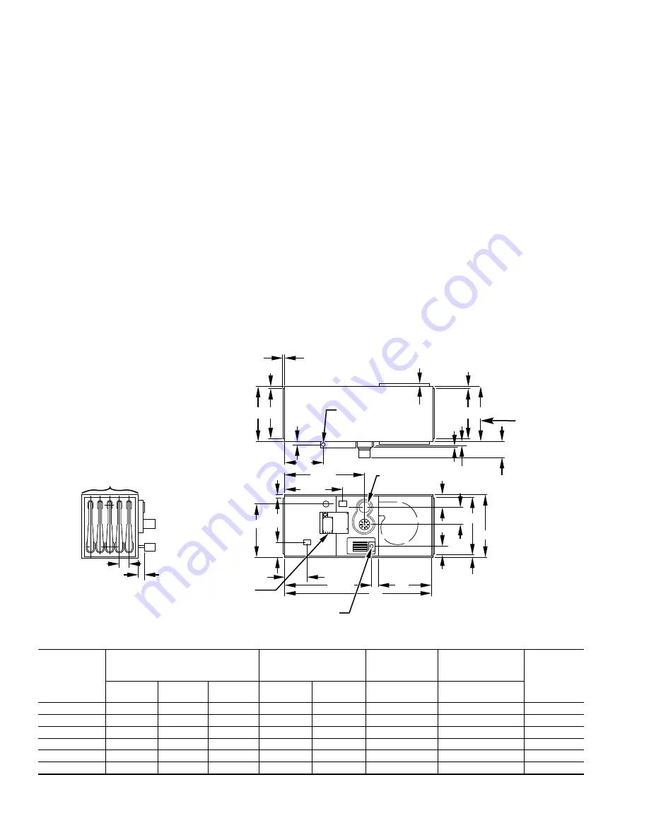
Fig. 1—Dimensional Drawing
Dimensions (In.)
UNIT SIZE
UNIT DIMENSIONS
DUCT SUPPLY
AND RETURN
OPENINGS
EXTENDED
BLOWER
DOOR*
NUMBER
OF HEAT
EXCHANGERS
NET
WEIGHT
(LB)
Length
Width
A
Height
Width
B
Height
C
D
050-12
50
13-1/2
23-1/8
11-5/8
21-3/8
Flush
2
112
075-12
50
13-1/2
23-1/8
11-5/8
21-3/8
Flush
3
121
075-16
50
13-1/2
23-1/8
11-5/8
21-3/8
1
3
125
100-16
50
17
23-1/8
15-1/8
21-3/8
Flush
4
141
100-20
50
17
23-1/8
15-1/8
21-3/8
1
4
149
125-20
50
20-1/2
23-1/8
18-5/8
21-3/8
Flush
5
161
* High airflow units only.
A96068
5
⁄
16
″
A B
5
⁄
8
″
2
1
⁄
2
″
7
⁄
8
-IN.
ELECTRICAL
CONNECTION
5
⁄
16
″
5
⁄
8
″
6
5
⁄
16
″
4
1
⁄
8
″
4
9
⁄
16
″
21
3
⁄
8
″
23
1
⁄
8
″
19
1
⁄
4
″
26
5
⁄
8
″
10
″
7
⁄
8
″
19
1
⁄
2
″
5
5
⁄
8
″
7
″
3
1
⁄
2
″
1
3
⁄
4
″
28
7
⁄
8
″
50
″
18
″
7
⁄
8
″
5
7
⁄
8
″
T-STAT
CONNECTION
AIR FLOW
1
7
⁄
8
″
A
B
C
4-IN. DIA VENT
CONNECTION
D ( NUMBER OF TUBES)
1
⁄
2
-IN.
GAS CONNECTION
(EXTEND BLOWER DOOR)
(HIGH AIR FLOW UNITS ONLY)
(2 PLACES)
2


