background image

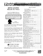
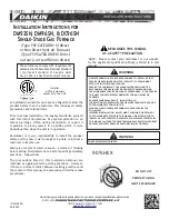
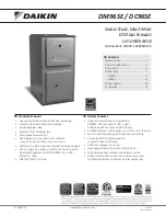
Summary of Contents for 58MCA series

Page 1: ...ing Legs If Desired 14 Installation In Lpflow and Downflow Applications 15 Installation In Horizontal Applications 15 Air Ducts 5 General 5 Ductwork Acoustical Treatment 17 Supply Air Connections 18 Return Air Connections 18 Fiher AxTangement 18 Bottom losure Panel 8 Gas Piping 19 Electrical onnections 20 115 v Wiring 21 24 v Wiring 21 Accesso ies 2 l Direct Venting 22 Removal of Existing Furnaces...

Page 2: ...b For 1200 CFM 20 in round or 14 _ x 19 _4n rectangle c For 1600 CFM 22 in round or 14 2 x 23 _ in rectangle d For airflow requirements above I800 CFM see Air Delivery table in Product Data literature for specific _se of single side inlets The use of both side inlets a combination of side and the bottom or the bottom only will ensure adequate return air openings for airflow requirements above 1800...

Page 3: ...ghlight suggestions which will result in enhanced installation reliability or operation The 58MCA Multipoise ondensing GasoFired Furnaces are CSA fPm_erly AGA and GA design certified for natural and propane gases see ffN nace rating plate and fPr installation in alcoves attics basements closets utility rooms crawlspaces and garages The furnace is factory shipped for use with natural gas A CSA list...

Page 4: ... prefabriquee maison mobile si prescrti Far la plaque signal6fique et si I on uti ise une trousse spacifiee par ta fabricant Cette fournaise peut _tre insta lee sur un p_ancber combustibe darts un enfoncement ou un placard en observant tas Dg Jagement M nimum En Pouces Avec El_reents De Construction Combustibles Cette fournaise n cesstie un systeme devacuation special La rnetbede dinstallation et ...

Page 5: ...rts 3 4 5 A B E and H the state of Massachusetts This product must be installed by a licensed plumber or gas fitter When flexible connectors are used the n_axinmm length shall not exceed 36 inches When lever types gas shutot t_ are used they shall not exceed 36 inches Step 7 Electrical Connections US National Electrical ode N E ANSIiNFPA 70 2002 CANADA anadian Electrical ode CSA C22 1 ELECTROSTATI...

Page 6: ...E TRAP LO ATION FACTORY SHIPPED ORIENTATION The condensate trap is _hctory installed in the blower shelf and _5ctory connected for UPFLOW applications A factow supplied tube is used to extend the condensate trap drain connection to the desired furnace side for field drain attachment See Condensate Trap Tubing Factory Shipped Orientation section i r drain tube extension details See Fig 5 CONDENSATE...

Page 7: ... nected and modified for attachment See Condensate Trap Tubing Alternate pflow Orientation section for robing attachment 9 PLUG CAP _ COLLECTOR BOX DRAIN TUBE BLUE WHITE STRIPED COLLECTOR BOX TUBE PINK COLLECTOR BOX TUBE GREEN COLLECTOR BOX DRAIN TUBE BLUE CONDENSATE _ TRAP HOUSING DRAIN TUBE VIOLET A00289 Fig 7 Alternate Upflow Tube Configuration and Trap Location To relocate condensate trap to t...

Page 8: ... and white striped label This robe is plugged to prevent condensate leakage in this application Ensure this robe is plugged O DRAIN TUBE BLUE TUBE PINK COLLECTOR BOX TUBE GREEN COLLECTOR BOX EXTENSION TUBE COLLECTOR BOX DRAIN TUBE BLUE WHITE STRIPED COLLECTOR BOX EXTENSION TUBE DRAIN TUBE COUPLING DRAIN TUBE VIOLET CONDENSATE TRAP BOX EXTENSION DRAIN TUBE Fig 9 Downflow Tube Configuration Right Ha...

Page 9: ...into collector box drain robe blue and white striped label which was previ ously plugged b onnect larger diameter drain robe factoo supplied in loose parts bag to drain tube cou pling extending collector box drain robe fbr connection to condensate trap c Route extended collector box drain robe directly fi om collector box drain to condensate txap as shown in Fig 9 d Determine appropriate length an...

Page 10: ... To relocate condensate trap from the blower shelf to desired location perform the tbllowing 1 Remove 3 tubes connected to condensate trap 9 10 2 Remove trap from blower shelf by gently pushing tabs inward and rotating trap 3 Install casing hole filler cap fi_ctmT supplied in loose parts bag into blower shelf hole where trap was removed CARBON MONOXIDE POISONING HAZARD Failm e to llow this warning...

Page 11: ...vent pipes are restricted to a mini mma_ length of 5 it See Table 7 NOTE A 12 in minimum offset pipe section is recommended with short 5 to 8 ft vent systems This recommendation is to reduce excessive condensate droplets fiom exiting the vent pipe See Fig 11 or 34j Step 5 Horizontal Right SupplyoAir Discharge Applications A horizontal right furrmce application is where furnace blower is located to...

Page 12: ...to check for proper connections COLLECTOR BOX DRAIN TUBE BLUE AND WHITE STRIPED 1 ollector Box Drain Tube a Remove _ctoryoinstalled plug from LOWER collector box drain robe blue and white striped label b Install removed clamp and plug into UPPER collector box ain tube blue label which was previously connected to condensate trap c Connect LOWER collector box drain robe blue and white striped label ...

Page 13: ...ed below fire ace See Fig 5 tbr dimensions The drain connection to condensate trap must also be properly sloped to an open ain NOTE Combustion air and vent pipes are restricted to a mini mum length of 5 fi See Table 7 NOTE A 12 in minimun_ offset pipe section is recommended with short 5 to 8 ft vent systems This recommendation is to reduce excessive condensate oplets fi om exiting the vent pipe Se...

Page 14: ...ctions 9 BACK A93043 Fig 14 ProNbit InstNtation on Back Step 3 Hazardous Locations FIRE EXPLOSION IN J R OR DEATH HAZARD Improper location or inadequate protection could result in fire or explosion When the ftlrnace is installed in a residential garage_ fl _e burners and ignition sources must be located at least 18 in above the floor The filrnace must be located or protected to avoid physical dama...

Page 15: ...ward as shown in Fig 21 This will affect airflow across heat exchangers and may cause limit cycling or premature heat exchanger _hilure Remove duct flange completely or bend it inward a minimum of 210 as shown in Fig 2 NOTE For 140 size unit when installed in downflow orientation cut the white jumper wire offbetween tem_inals PL1 7 and PLI 9 Do not cut white jumper between terminals PLI 7 and PL I...

Page 16: ...D5 or CK5 Coil Assembly or KCAKC Coil Box Upftow Applications 20 1 8 Downflow Applications on Non Combustible Flooring 20 21 Downflow Applications on Combustible Flooring Using KGASB Subbase 20 1 4 Furnace with or without CD5 or CK5 Coil Assembly or KCAKC Coil Box Downflow Applications on Combustible Ftoodng NOT Using KGASB Subbase 20 Furnace with CD5 or CK5 Coil Assembly or KCAKC Coil Box Upflow ...

Page 17: ...cessible when the fi mace is installed arid shall be of such a size that d_e heat exchanger can be viewed fbr possible openings using light assistance or a probe can be inserted fbr sampling the air stream The cover attachment shall prevent leaks DUCTWORK AC USTICAL TREATMENT Metal duct systems that do not have a 90 degree elbow and 10 ft of main duct to the first branch take off may require inter...

Page 18: ... may be attached into unused side return air portion of the fi mace casing DO NOT connect any portion of return air duct to back of furnace casing Downflow and Horizontal Furnaces The return air duct must be connected to end inlet opening provided as shown in Fig 2 DO NOT cut into casing sides or back to attach any portion of return air duct Bypass humidifier connec tions should be made at ductwor...

Page 19: ...fbr gas leaks with an open flame Use a commercially available soap solution made specifically fbr the detection of leaks to check all connections Use proper length of pipe to avoid stress on gas contlol manifold If a flexible connector is required or allowed by aud _ority having jurisdiction black iron pipe shall be installed at Nmace gas valve and extend a minimum of 2 in outside Nmace casing Ins...

Page 20: ... leak tested in accordance with NFG in the United States or NSCNGPIC in Canada local and national plumbing and gas codes before the Nrnace has been connected ARer all connections have been made purge lines and check for leakage at furnace prior to operating Nrnace If pressure exceeds 0 5 psig 14 in wc gas supply pipe must be disconnected from fl mace and capped befbre pressure test If test pressur...

Page 21: ...d according to NEC ANSI NFPA 70 2002 and Canadian Elec tdcal 7ode CSA 22 1 or local codes to minimize personal injm T if an electrical fhult should occur This may consist of electrical wire or condtlit approved for electrical ground when installed in accordance with existing electrical codes Do not use gas piping as an electrical ground J Box Relocation 1 Remove 2 screws holding auxiliary J box Se...

Page 22: ...mbustion products into the living space etc ARBON MONOXIDE POISONING HAZARD Failure to J btlow the steps outlined below for each appliance connected to the venting system being placed into operation could result in carbon monoxide poisoning or death The following steps shall be tbllowed for each appliance connected to the venting system being placed into operation while all other appliances connec...

Page 23: ...UIT IDM EXTENSION CONNECTOR PRESSURE SWITCH SPS N O COMPONENT TEST T_A INTERMINAL TRANSFORMER 115VACi24MAC JUNCTION UNMARKED TERMINAL PCB CONTROL TERMINAL FACTORY WIRING 115VAC FACTORY WIRING 24 VAC FIELD WIRING 115VAC FIELD WIRING 24MAC CONDUCTOR ON CONTROL PCB FIELD WIRING SCREW IT RMINAL FIELD EARTH GROUND EQUIPMENT GROUND RELD SPLICE PLUG RECEPTACLE COM p_ 24V NOTE _6 NOTES 1 ffar_yat the a gl...

Page 24: ...nada constluct all combustion aft and vent pipes fbr this unit of SA or ULC listed schedule40 PV PVC DWV or ABS DWV pipe and pipe cement SDR pipe is NO7 approved in anada NOT IN HORIZONTAL SECTION FURNACE TRANSITION IN VERTICAL SECTION See Table 7 for maximum pipe lengths and Fig 36 37 38 39 and 40 fbr exterior piping an angements NOTE Fm nace combustion air and vent pipe connections are sized fbr...

Page 25: ...re to contaminated combustion air may result in safety and perfbrmance related problems ombustion air must not be taken flom inside structure because inside air is frequently contaminated by halogens which include fluorides chlorides bromides and iodides These elements are fbund in aerosols detergents bleaches cleaning solvents salts air ffesheners adhesives paint and other household products Loca...

Page 26: ... I5 kW K Clearance to a mechanical air supply inlet 6 1 83 m 3 91 cm above if within 10 3m horizontally L Clearance under a veranda porch deck or balcony 12 30 cm M Clearance to each side of the centedine extended above or 12 30 cm 12 30 cm below vent terminat of the furnace to a dryer or water heater vent or other appliances direct vent intake or exhaust N Clearance to the vent terminal of a drye...

Page 27: ...nt Solvent Cement Solvent Cement Primer Schedule 40 Schedule 40 For ABS SDR 21 SDR 26 Schedule 4O Schedule 40 For PVC DWV at Schedule 40 IPS sizes DWV Schedule 40 Schedule 40 SDR For CPVC Cellular Core DWV at Schedule 40 IPS sizes For PVC Cettular Core Schedule 40 DWV VENT PiPE PiPE HORIZONTALTO ROOF HORIZONTAL TO SIDEWALL COMBUSTION AIRPIPE J _ COMBUSTION AIR PIPE _ 3 _ F VENT PIPE VERTICAL TO RO...

Page 28: ...or by illing a 1i8 im hole in fitting using hole in intake housing as a guide Install a field supplied No 6 or No 8 sheet metal screw NOTE DO NOT OVER TIGHTEN SCREW Breakage of intake housing or fitting may cause air leakage to occur A plugged ain connection has been provided on this fitting _br use when moisture is _bnnd in combustion air intake pipe and combustion box NOTE Moisture in conft_usti...

Page 29: ... 2 2 1 2 3 31 no disk 41 no disk 31 one disk 31 no disk 41 no disk NUMBER OF 90 ELBOWS 1 2 3 4 5 6 5 NA NA NA NA NA 70 70 65 60 60 55 70 70 70 70 70 70 20 15 10 5 NA NA 70 70 70 70 70 70 10 NA NA NA NA NA 55 50 35 30 30 20 70 70 70 70 70 70 5 NA NA NA NA NA 40 30 20 20 10 NA 70 70 70 70 70 70 10 NA NA NA NA NA 45 40 35 30 25 20 70 70 70 70 70 70 5 NA NA NA NA NA 40 35 30 25 20 15 60 56 52 48 44 40...

Page 30: ...oncentric 2 Pipe or 2 in Concentric 2 Pipe or 3dn Concentric 2 Pipe or 3 in Concentric PIPE DmA fiN 1 1 2 2 1 1 2 2 2 2 1 2 2 1 2 3 31 no disk 41 no disk 31 no disk 41 no disk PIPE DtA IN 1 1 2 2 1 1 2 2 2 2 1 2 2 1 2 3 31 no disk 41 no disk 3 no disk 41 no disk PIPE DIA IN 1 1 2 2 1 1 2 2 2 2 1 2 2 1 2 3 31 no disk 41 no disk 41 no disk PIPE DIA IN 1 1 2 2 1 1 2 2 2 2 1 2 2 1 2 3 31 no disk 41 no...

Page 31: ...h pipes 3 Assume two 45 elbows equal one 90 etbow Long radius elbows are desirable and may be required in some cases 4 Elbows and pipe sections within the furnace casing and at the vent termination should not be included in vent length or elbow count 5 The minimum pipe length is 5 ft for all applications 6 Use 3 in diameter vent termination kit for installations requiring 4 in diameter pipe COMBUS...

Page 32: ... air pipe Roof terminations Loosely install pipe coupling on prop erly cut vent pipe Coupling must be positioned so bracket will mount as shown in Fig 36 For applications using combustion air pipe option indicated by dashed lines in Fig 36 install 90 _ street elbow into 90 _ elbow making U fitting A 180 _ U fitting may be used Sidewall terminations Install bracket as shown in Fig 39 or 40 For appl...

Page 33: ... OF COMBUSTION AIR AND OF VENT 12 IN CLEARANCE ABOVE HIGHEST ANTICIPATED SNOW LEVEL OR GRADE COMBUSTION AIR WHICHEVER IS GREATER A87224 12IN CLEARANCE ABOVE HIGHEST ANTICIPATED SNOW LEVEL OR GRADE WHICHEVER IS GREATER A93055 Fig 38 Concentric Vent and Combustion Air Side Termination OVERHANG OR ROOF 12 MINIMUM _ _ _ COMBUST ON A R _ _ 7_ _ j _ _ BOTTOM OF VENT _ r_ _ _ J_ _ _MAINTAIN 12 IN L _ CLE...

Page 34: ...tion _j j J j COMBUSTION j _ _I_ _1_ dENT A93057 Fig 43 Concentric Vent and Combustion Air Side Termination Dimension A is Touching or 2 In Maximum Separation COMBUSTION AIR J COMBUSTION AIR COMBUSTION AIR A96129 Fig 44_Sidewal Termination of 12 in or Less Dimension A is Touching or 2 In Maximum Separation 34 A96130 Fig 45 Sidewai Termination of More Than 12 in Dimension A is Touching or 2qn Maxim...

Page 35: ...ondensate trap or drain robe coupling is sized for 1 2 in PVC 1i2 im PV _ or 5 8 in ID robe connection Drain pipe and fittings must con_bm Go ANSI standards and ASTM D1785 D2466 or D2846 CPV or PVC cement must conform to ASTM D2564 or F493 Primer must conform to ASTM F656 In Canada use CSA or ULC listed schedule 40 CPVC or PV drain pipe fittings and cement When a condensate pump is required select...

Page 36: ...pidly and furnace will not ope ate 2 Thermostat wire connections at terminals R W G and Y n rest be made at 24 v terminal block on fi rnace control center 3 Natural gas sela ice pressure must not exceed 05 psig 14 in wc but must be no tess than 016 psig 4 5 in wc 36 CONDENSATE WIRE TIE HEAT 3 WRAPS MINIMUM A93036 Fig 4g Condensate Trap Heat Tape 4 Blower access panel must be in place to complete l...

Page 37: ...he control CPU will repeat the ignition sequence for up to three more Trials For Ignition befbre going to Ignition Lockout Lockout will be reset attto matically after three hours by momentarily interrupting 115 vac power to the furnace or by internlpfing 24 vac power at SEC1 or SEC2 to the furnace control CPU not at W G R etc If flame is proved when flame should not be present the fhrnace control ...

Page 38: ... energized when the blower is energized This ftamre helps diagnose a system problem in case of a component failure The component test fbature will not operate if any them_ostat signal is present at the control and not until all time delays are completed NOTE Record the status code BEFORE opening the blower access door and befbre shutting offpower to the fhrnace Opening the blower access door wil o...

Page 39: ...enclosure front INSTALLED a Remove burner enclosure fiont b Remove cap that conceals adjustment screw for gas valve regulator See Fig 50 c Jumper R and W thermostat connections on control to start _ fnace d Turn adjusting screw counterclockwise out to decrease manifold pressure or clockwise in to increase manifbld pressure NOTE This furnace has been approved r a mani ld pressure of 32 in wc to 38 ...

Page 40: ...4 3 4 44 3 5 44 3 2 44 3 3 48 3 7 45 3 8 45 3 5 45 3 0 45 3 4 45 3 5 SPECIFIC GRAVITY OF NATURAL GAS 0 58 0 50 0 02 Orifice Manifold Orifice Manifold Orifice Manifotd No Pressure No Pressure No Pressure 43 3 8 42 3 2 42 3 3 43 3 5 43 3 7 43 3 8 44 3 8 43 3 4 43 3 6 44 3 6 44 3 7 44 3 8 44 3 4 44 3 5 44 3 6 44 3 2 44 3 3 44 3 4 45 3 7 45 3 8 44 3 2 45 3 5 45 3 5 45 3 7 45 3 3 45 3 4 45 3 5 45 3 t 4...

Page 41: ...ld No Pressure No Pressure No Pressure 42 3 2 42 3 3 42 3 4 43 3 7 43 3 8 42 3 2 43 3 4 43 3 5 43 3 7 44 3 7 44 3 8 43 3 4 44 3 5 44 3 6 44 3 7 44 3 3 44 3 4 44 3 5 48 3 7 44 3 2 44 3 3 45 3 8 48 3 8 45 3 8 45 3 3 48 3 4 45 3 8 45 3 2 45 3 3 45 3 4 SPECIFIC GRAWTY OF NATURAL GAS 8 88 Orifice Manifold No Pressure 43 3 7 43 3 5 44 3 7 44 3 5 44 3 3 48 3 7 48 3 8 48 3 3 48 3 1 48 3 0 45 2 8 48 2 7 45...

Page 42: ...3 4 44 3 5 48 3 8 44 3 3 48 3 8 48 3 7 45 8 4 48 8 8 48 3 2 48 3 3 48 3 0 45 3 1 0 84 0 88 Orifice Manifold Orifice Manifold No Pressure No Pressure 42 3 5 42 3 6 42 3 2 42 3 3 43 3 6 43 3 7 43 3 4 43 3 5 44 3 6 44 3 7 44 3 4 44 3 5 48 3 8 44 3 3 48 8 8 48 8 7 48 8 4 48 8 8 48 8 2 45 3 8 SPECIFIC GRAVITY OF NATURAL GAS 0 80 0 82 Orifice Manifold Orifice Manifold No Pressure No Pressure 42 3 3 42 3...

Page 43: ...ice Manifold No Pressure No Pressure No Pressure 41 3 8 40 3 6 40 3 8 41 3 6 41 3 7 41 3 8 42 3 8 41 3 5 41 3 6 42 3 6 42 3 7 42 3 8 42 3 4 42 3 5 42 3 6 42 3 2 42 3 3 42 3 4 43 3 7 42 3 2 42 3 3 43 3 6 43 3 7 43 3 8 43 3 4 43 3 9 43 3 9 43 3 2 43 3 3 43 3 4 44 9 5 43 3 2 43 3 3 SPECIFIC GRAVITY OF NATURAL GAS 0 99 Orifice Manifold No Pressure 41 3 8 41 3 6 42 3 7 42 3 5 42 3 3 43 3 8 43 3 6 43 3 ...

Page 44: ... 3 43 3 4 43 3 1 43 3 2 43 2 9 43 3 0 0 54 0 65 Orifice Manifold Orifice Manifold No Pressure No Pressure 40 3 6 40 3 8 41 3 7 41 3 8 42 3 8 41 3 6 42 3 6 42 3 7 42 3 4 42 3 5 42 3 2 42 3 3 43 3 7 43 3 8 43 3 5 43 3 5 43 3 3 43 3 4 43 3 1 43 3 2 SPECIFIC GRAWTY OF NATURAL GAS 0 50 0 52 Orifice Manifold Orifice Manifold No Pressure No Pressure 41 3 7 41 3 8 42 3 8 41 3 5 42 3 5 42 3 7 42 3 3 42 3 4...

Page 45: ... 12 0 89 6001 7000 12 14 0 87 7001 8000 14 16 0 85 8001 9000 16 18 0 83 9001 10 000 18 20 0 81 Derate multiplier factor Js based on midpoint altitude for altitude range b Reinstall burner box cover c Gas valve regulator seal cap MUST be on d Turn off all other gas appliances and pilots e Start furnace and let operate for 3 minutes Measure time in sec fbr gas meter test dial to complete 1 revolutio...

Page 46: ...gs stabilize subtract return air tern peramre t rom supply air temperature to determine air tern perature rise 3 Adjust temperature rise by adjusting blower speed Increase blower speed to reduce temperature rise Decrease blower speed to increase temperature rise ELECTRICAL SHOCK HAZARD Failure to fbllow this warning could result in personal injury or death Disconnect 115 v electrical power before ...

Page 47: ...ower to I_urnace 2 Remove main furnace door and disconnect inducer motor lead wires ti om wire harness 3 Turn on 115 v power to furnace 4 Set thermostat to call for heat and wait 1 minute When pressure switch is functioning properly hot surfhce igniter should NOT glow and control stains code LED flashes a Stares Code 31 If hot surfitce igniter glows when inducer motor is disconnected shut furnace ...

Page 48: ...Drain Connection Leak Tight and Sloped Condensate Trap Primed before Start Up Heat Tape Installed if Required CHECKUST START UP Gas Input Rate Set Within 2 percent of Rating Plate Temperature Rise Adjusted Thermostat Anticipator Anticipator Setting Adjusted or Cycle Rate 3 Cycles per Hr Selected Safety Controls Cheek Operation Primary Limit Pressure Switch Low Ambient Exposed Pipes Copyright 2005 ...

Reviews: