background image

2-4

T-296

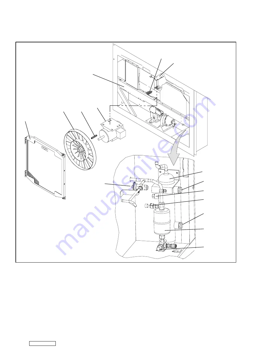
2.1.5 Air Cooled Condenser Section

The air cooled condenser section (Figure 2-4) consists

of the condenser fan, condenser coil, receiver with sight

glass/moisture indicator, quench valve, manual liquid

line valve, filter-drier, condenser pressure transducer

and fusible plug.
The condenser fan pulls air in the bottom of the coil and it

is discharged horizontally out through the condenser fan

grille.

5

6

7

15

1

2

4

3

8

10

9

11

13

12

14

1. Grille and Venturi Assembly

2. Condenser Fan

3. Key

4. Condenser Fan Motor

5. Condenser Coil Cover

6. Condenser Coil

7. Condenser Motor Mounting Bracket

8. Receiver

9. Sight Glass

10. Fusible Plug (Rupture Disc -- Alternate)

11. Condenser Pressure Transducer

12. Sight Glass/Moisture Indicator

13. Filter-Drier

14. Liquid Line Service Valve

15. Quench Valve

Figure 2-4 Condenser Section

Downloaded from 

ManualsNet.com

 search engine

Summary of Contents for 69NT40-511-310

Page 1: ...T 296 Rev A Carrier Transicold Container Refrigeration Operation Service Models 69NT40 511 310 344 359 Downloaded from ManualsNet com search engine...

Page 2: ...ONTAINER REFRIGERATION UNIT Models 69NT40 511 310 344 359 Carrier Transicold Carrier Corporation P O Box 4805 Syracuse N Y 13221 U S A Carrier Transicold Division A member of the United Technologies C...

Page 3: ...g bridging an overload or using any sort of jumper wires Problems with the system should be diagnosed and any necessary repairs performed by qualified service personnel When performing any arc weldin...

Page 4: ...ndenser fan grille before turning power OFF and disconnecting power plug WARNING Oakite No 32 is an acid Be sure that the acid is slowly added to the water DO NOT PUT WATER INTO THE ACID this will cau...

Page 5: ...user depresses the ENTER key CAUTION The unit will remain in the DEFROST mode as long as the emergency defrost switch is in the DE FROST position To prevent cargo damage the operator must monitor con...

Page 6: ...be OFF whenever a programming card is inserted or removed from the controller pro gramming port CAUTION All 69NT40 511 3XX units must use software revision 5108 or higher to enable stepper motor Opti...

Page 7: ...e Monitoring 1 1 1 3 9 Communications 1 1 1 3 10 Compressor 1 1 1 3 11 Condenser Coil 1 2 1 3 12 Autotransformer 1 2 1 3 13 Temperature Recorder 1 2 1 3 14 Gutters 1 2 1 3 15 Handles 1 2 1 3 16 Thermo...

Page 8: ...3 2 CONTROLLER SOFTWARE 3 3 3 2 1 Configuration Software Configuration Variables 3 3 3 2 2 Operational Software Function Codes 3 3 3 3 MODES OF OPERATION 3 3 3 3 1 Temperature Control Perishable Mode...

Page 9: ...ith Condenser Fan Switch 4 2 4 5 CONNECT REMOTE MONITORING RECEPTACLE 4 2 4 6 STARTING AND STOPPING INSTRUCTIONS 4 2 4 6 1 Starting the Unit 4 2 4 6 2 Stopping the Unit 4 2 4 7 START UP INSPECTION 4 2...

Page 10: ...e system 6 3 6 6 4 Procedure Partial System 6 4 6 7 REFRIGERANT CHARGE 6 4 6 7 1 Checking the Refrigerant Charge 6 4 6 7 2 Adding Refrigerant to System Full Charge 6 4 6 7 3 Adding Refrigerant to Syst...

Page 11: ...rocedures 6 18 6 19 AUTOTRANSFORMER 6 19 6 20 CONTROLLER 6 19 6 20 1 Handling Controller 6 19 6 20 2 Controller Trouble Shooting 6 19 6 20 3 Controller Programming Procedure 6 20 6 20 4 Removing and I...

Page 12: ...n Mode 4 7 Figure 4 8 Defrost 4 7 Figure 6 1 Service Valve 6 1 Figure 6 2 Manifold Gauge Set 6 1 Figure 6 3 R 134a Manifold Gauge Hose Set 6 2 Figure 6 4 Refrigeration System ServiceConnections 6 2 Fi...

Page 13: ...Units with PID Number 0712 7 5 Figure 7 5 WIRING DIAGRAM Units with PID Number 0712 7 7 Figure 7 7 WIRING DIAGRAM Units with PID Number 0881 7 9 LIST OF TABLES TABLE NUMBER Page Table 2 1 Safety and P...

Page 14: ...e www container carrier com 1 3 OPTION DESCRIPTION Various options may be factory or field equipped to the base unit These options are listed in the tables and described in the following subparagraphs...

Page 15: ...s may have access doors and or hinge mounting 1 3 19 460 Volt Cable Various power cable and plug designs are available for the main 460 volt supply The plug options tailor the cables to each customers...

Page 16: ...ded with the latest software Note Repaired controllers are NOT to be used for warranty repairs only full OEM Remanufactured controllers are to be used Controllers will be factory equipped with the lat...

Page 17: ...is to provide ventilation for commodities that require fresh air circulation 1 2 3 6 4 9 5 10 12 7 13 11 8 14 1 Access Panel Evap Fan 1 2 Thermometer Port 3 Access Panel Heater Thermostatic Expansion...

Page 18: ...e accessible by removing the upper rear panel as shown in the illustration or by removing the front access panels 17 16 14 15 1 2 3 4 6 7 9 10 13 18 19 11 8 12 5 HTT Alternate Location 1 Evaporator Fa...

Page 19: ...at the right side of the compressor 10 1 2 3 4 5 6 7 9 12 13 14 15 16 17 18 8 11 1 Autotransformer 2 Power Cables and Plug 3 Compressor Sight Glass View Port 4 Compressor Guard 5 Return Temperature S...

Page 20: ...coil andit is discharged horizontally out through the condenserfan grille 5 6 7 15 1 2 4 3 8 10 9 11 13 12 14 1 Grille and Venturi Assembly 2 Condenser Fan 3 Key 4 Condenser Fan Motor 5 Condenser Coil...

Page 21: ...r pressure switch The water cooled condenser replaces the standard unit receiver 1 2 3 4 5 6 7 8 9 10 11 1 Sight Glass 2 Water Cooled Condenser 3 Rupture Disc 4 Condenser Pressure Transducer 5 Quench...

Page 22: ...master system technicalmanual for further information 16 17 18 12 14 15 1 2 3 4 5 6 7 10 9 19 11 8 13 20 21 1 Compressor Contactor 2 Heater Contactor 3 Display Module 4 Communications Interface Module...

Page 23: ...s 4 0 kg 8 8 lbs 4 9 kg 10 8 lbs NOTE When replacing the following components h i and j refer to the installation instructions included with the When replacing the following components h i and j refer...

Page 24: ...tor Coil Rating 750 watts 5 10 each 230 vac e Evaporator Coil Heaters Resistance cold 66 8 to 77 2 ohms 20 _C 68 _F Type Sheath 380 vac 50 hz 460 vac 60 hz Full Load Amps High Speed 1 6 2 0 Full Load...

Page 25: ...P EM Table 2 1 Safety and Protective Devices UNSAFE CONDITION SAFETY DEVICE DEVICE SETTING Circuit Breaker CB 1 Manual Reset Trips at 29 amps 460 vac Excessive current draw Circuit Breaker CB 2 50 amp...

Page 26: ...thermostatic expansion valve is activated by the bulb strapped to the suction line near the evaporator outlet The valve maintains a constant superheat at the coil outlet regardless of load conditions...

Page 27: ...BLE PLUG RECEIVER SERVICE VALVE WATER COOLED CONDENSER PRESSURE REGULATOR TXV TXV BULB EVAPORATOR CONDENSER PRESSURE TRANSDUCER SERVICE VALVE PRESSURE REGULATOR EVAPORATOR CONDENSER SERVICE VALVE SERV...

Page 28: ...e arctic drain line is attached to the drain pan and prevents water from freezing in the line In addition there is a crankcase heater CCH installed onto the compressor which warms the refrigerant oil...

Page 29: ...ORDER software is provided in paragraph 3 6 The key pad and display module serve to provide user access and readouts for both of the controller functions temperature control and DataCORDER The functio...

Page 30: ...r scroll a selection down ward Pre trip repeat backward Return Supply Displays non controlling probe tem perature momentary display _C _F Displays alternate English Metric scale momentary display When...

Page 31: ...without AC power con nected f Provide the ability to reprogram the software through the use of a memory card The memory card auto matically downloads new software to the controller when inserted 3 2...

Page 32: ...is less than or equal to 8 38 When the above conditions are met either pressures or timers may dictate a change of state from OFF to ON or ON to OFF If the condenser fan is OFF it will be energized if...

Page 33: ...ller de energizes the heat relay The controller will continue to cycle heating to maintain relative humidity below the selected set point If the mode is terminated by a condition other than the humidi...

Page 34: ...ue to cool until the previously mentioned off cycle temperature criteria are met If the control temperature is less than the set point 0 2_C the unit will turn off the evaporator fans and restart anot...

Page 35: ...ons Power supply battery pack The DataCORDER performs the following functions a Logs data at 15 30 60 or 120 minute intervals and stores two years of data based on one hour interval b Records and disp...

Page 36: ...re uses the supply and return recorder sensors The temperature control software uses the supply and return temperature sensors b Generic Mode The generic recording mode allows user selection of the ne...

Page 37: ...gin Origin Date Destination Discharge Date Comment DataLine Tool Probe Calibration Readings USDA1 0 0 USDA2 0 0 USDA3 0 0 Cargo 0 0 Temperature Units Centigrade _______________________________________...

Page 38: ...the stop start switch 2 Controller DC battery pack power If a battery pack is installed the DataCORDER will power up for communication when an interrogation cable is plugged into an interrogation rece...

Page 39: ...ur three pin receptacles are for the probes and fifth five pin receptacle is the rear connection forthe theInterrogator The probe receptacles are sized to accept plugs with tricam coupling locking dev...

Page 40: ...b To scroll to the end of the alarm list press the UP AR ROW Depressing the DOWN ARROW key will scroll the list backward c The left display will show AL where is the alarms number in the queue The rig...

Page 41: ...High Watt CnF19 Controlled Atmosphere Out No In Yes CnF20 Suction Pressure Sensor Out No In Yes CnF21 Autotransformer Out In CnF22 Economy Mode Option OFF Std Full CnF23 Defrost Interval Timer Save Op...

Page 42: ...is displayed Cd10 Compressor Suction Temperature Compressor suction temperature sensor reading is displayed Cd11 Compressor Dis charge Temperature Compressor discharge temperature sensor reading is di...

Page 43: ...return tempera ture sensor reading will be used Defrost Interval Timer Value Configuration variable CnF23 If the software is configured to SAv save for this option then the value of the defrost interv...

Page 44: ...NOTE If humidification CnF35 is enabled then humidification will be enabled and dehumidification locked out at set points of 75 and above At set points be low 75 dehumidification will be enabled and h...

Page 45: ...sor reading Cd39 Secondary Return Temperature Sensor Code Cd39 will display the current secondary return temperature sensor reading for units configured for four probes If the unit is configured with...

Page 46: ...porator fans and will re main active until the motor protector resets This alarm triggers the failure action code set by Function Code Cd29 AL25 Condenser Fan Mo tor Safety Alarm 25 is triggered by th...

Page 47: ...e compressor high discharge pressure safety switch remains open for at least one minute This alarm will remain active until the pres sure switch resets at which time the compressor will restart AL59 H...

Page 48: ...e Sensor Failure Alarm 69 is triggered by a suction temperature sensor reading outside the valid range of 60_C 76_F to 150_C 302_F This is a display alarm and has no associated failure action NOTE If...

Page 49: ...e unit is configured for single evaporator fan operation Pre Trip tests P3 0 P3 1 P4 0 and P4 1 will fail immediately if Controller alarm codes AL11 or AL12 are active at the start of testing P3 0 Low...

Page 50: ...rom the previous test The quench valve if configured will operate as in normal control mode The SMV is closed to 0 open current and condenser pressure readings are taken The SMV is opened to 50 with c...

Page 51: ...e exceeds 27 42 kg cm2 390 psig P7 1 High Pressure Switch Open Requirements Test P7 0 must pass for this test to execute Setup The con denser fan is started and a 60 second timer is started Pass Fail...

Page 52: ...above 7_C 45_F If the container temper ature is below 7_C a 180 minute timer will be started the set point will be set to 7_C and the control will be placed in normal heat The left display will read P...

Page 53: ...S N Left 4 Right 4 The DataCORDER serial number consists of eight characters Function code dC26 contains the first four characters Function code dC27 contains the last four characters This serial numb...

Page 54: ...Fail Skip Result Change in currents for Phase A B and C 6 1 Not Applicable Not Used 6 2 Suction Modulation Valve Open and Closed Pass Fail Skip Result Is current or pressure limit in effect Y N 6 4 N...

Page 55: ...ork Data Point 1 8 Out of Range The network data point is outside of its specified range The DataCORD ER is configured by default to record the supply and return recorder sen sors The DataCORDER may b...

Page 56: ...230 vac Power An autotransformer Figure 4 1 is required to allow operation on nominal 230 volt power It is fitted with a 230 vac cable and a receptacle to accept the standard 460 vac power plug The 23...

Page 57: ...or will stop and remain stopped until the CFS switch is set to position I CAUTION When condenser water flow is below 11 lpm 3 gpm or when water cooled operation is not in use the CFS switch MUST be se...

Page 58: ...ries of individual pre trip tests The user may also scroll down to select any of the individual tests The contents of the menus are as follows PRE TRIP SELECTION MENU Auto or Auto 1 Auto 2 Auto 3 P P1...

Page 59: ...installed it will be operational whenever the compressor is off and there is power to the unit The heater is connected to a set of normally closed auxiliary contacts on the compressor contactor 4 9 2...

Page 60: ...RCULATION AIR CIRCULATION MODULATING COOLING 2 5_C 4 5_F Figure 4 3 Controller Operation Perishable Mode AIR CIRCULATION ONLY SET POINT FALLING TEMPERATURE RISING TEMPERATURE 1 5_C 2 7_F 1_C 1 8_F 0 5...

Page 61: ...essor and con denser fan motors The cool light is also de ener gized f The evaporator fan motors continue to run to circulate air throughout the container The in range light re mains illuminated as lo...

Page 62: ...eported by the supply and re turn probes 5 The controller Demand Defrost configuration vari able CnF40 is set to In and the unit has been in pull down operation for over 2 5 hours without reach ing se...

Page 63: ...tes in this condition At the end of the eight minutes probe alarms will be set or cleared based on the conditions seen When the return air falls to 7_C 45_F the controller checks to ensure the defrost...

Page 64: ...mination thermostat open Replace Low line voltage Check Compressor hums but does not Single phasing Check Compressor hums but does not start Shorted or grounded motor windings 6 8 Compressor seized 6...

Page 65: ...16 Unit will not heat or has insuffi Evaporator fan motor contactor defective Replace Unit will not heat or has insuffi cient heat Controller malfunction 5 9 Defective wiring Replace Loose terminal c...

Page 66: ...sive frost on evaporator coil 5 6 Evaporator fan s rotating backwards 6 16 3 Discharge pressure regulator valve defective Replace Suction modulation valve malfunction 6 18 Suction and discharge pres H...

Page 67: ...ial in valve Hi h i i h l Superheat setting too low 6 14 High suction pressure with low superheat External equalizer line plugged Ice holding valve open Open superheat Foreign material in valve 6 14 L...

Page 68: ...m Cap 4 Valve stem 5 Compressor Or Filter Drier Inlet Connection Figure 6 1 Service Valve OPENED Backseated HAND VALVE CLOSED Frontseated HAND VALVE SUCTION PRESSURE GAUGE DISCHARGE PRESSURE GAUGE A B...

Page 69: ...e gauge set 6 To read system pressures slightly midseat the high side and suction service valves 6 4 5 7 BLUE D S 10 1 2 3 8 YELLOW 9 RED 13 11 12 1 Discharge Service Valve 2 Compressor 3 Suction Serv...

Page 70: ...n are copper plating acid sludge formation freezing up of metering devices by free water and formation of acids resulting in metal corrosion 6 6 2 Preparation a Evacuate and dehydrate only after press...

Page 71: ...mpressor dis charge and suction service valves For units operat ing on a water cooled condenser change over to air cooled operation b Bring the container temperature to approximately 1 7_C 35_F or 17...

Page 72: ...aragraph 2 2 for weight of compressor g Remove high pressure switch HPS from compres sor and check operation of switch refer to paragraph 6 9 2 1 2 3 4 5 6 7 8 10 11 12 13 14 15 9 16 1 Discharge Valve...

Page 73: ...is stuck tap the center of the cylinder head with a wooden or lead mallet Do not strike the side of the cylinder head Be careful not to drop the head or dam age the gasket sealing surface Remove cyli...

Page 74: ...ner Screws and Washers 2 Suction Strainer 3 Motor End Cover Gasket 4 Motor End Cover 5 Valve Gasket 6 Suction Service Valve 7 Valve Capscrew Figure 6 11 Motor End Cover i Remove the refrigerant suctio...

Page 75: ...leakage 1 3 2 1 Suction Valve 2 Suction Valve Positioning Spring 3 Valve Plate Dowel Pin Figure 6 14 Suction Valve Positioning Springs Suction valves are positioned by dowel pins see Figure Figure 6 1...

Page 76: ...e unit in cooling mode for at least 20 min utes 2 Check the front oil sight glass on the compressor to ensure that no foaming of the oil is present after 20 minutes of operation If the oil is foaming...

Page 77: ...se pressure on switch The switch should open at a static pressure up to 25 kg cm 350 psig If a light is used light will go out If an ohmmeter is used the meter will indicate open circuit g Slowly open...

Page 78: ...as a liquid in cases each containing 3 785 liters 4 U S gallon bottles and also in carboys of 52 6 kg 116 lbs net 3 Fresh clean water 4 Acid proof pump and containers or bottles with rub ber hose NOT...

Page 79: ...sh the tubes thoroughly with fresh water NOTE If the condenser cooling water is not being used as drinking water or is not re circulated in a closed or tower system neutralizing is not nec essary 11 P...

Page 80: ...lve d Set the temperature set point to 18_C 0_F and run unit until conditions stabilize e The readings may cycle from a high to a low reading Take readings of temperature and pressure every three to f...

Page 81: ...6 14 1 6 14 3 Semi Hermetic Valve Replacement a Removing Expansion Valve 1 Pump down the unit per paragraph 6 4 2 Remove insulation Presstite from expansion valve bulb and power assembly and then remo...

Page 82: ...curing heaters to coil e Lift the bent end of the heater with the opposite end down and away from coil Move heater to the side enough to clear the heater end support and remove 6 16 EVAPORATOR FAN AND...

Page 83: ...e motor and may be removed by two methods 1 If container is empty open upper rear panel of the unit The capacitor may be serviced after discon necting power plug 2 If container is full turn the unit p...

Page 84: ...rent box temperature so the unit goes into pulldown Run the unit for approximate ly one minute Record readings on gauges and cur rent draw The current draw and pressures should go up Place set point t...

Page 85: ...olt meter There should be approximately 24 to 32 VDC shown on pin A e There should be zero volts on pin B f After a short delay the reading should rise to approx imately 24 to 32 VDC on pin E g Pins C...

Page 86: ...t will provide a static free work surface on which to place and or service the controller b Disconnect and secure power to the unit c Place strap on wrist and attach the ground end to any exposed unpa...

Page 87: ...per model dash number For example to program a model number 69NT40 511 100 press the UP or DOWN ARROW key until the display shows 511 on the left display and 100 on the right If a defective card is be...

Page 88: ...s the black wire should be cut at the middle length and the red white wire cut to the shorter length See Figure 6 27 Sensor 40 mm 1 1 2 inch 6 3 mm 1 4 inch Mounting Stud Type Sensor 40 mm 1 1 2 inche...

Page 89: ...al section of the sensor against the the side of the mounting clamp c Sensor DTS The DTS sensor must have insulating material placed completely over the sensor to insure the coil metal temperature is...

Page 90: ...charge is too low to enable recording during the power off period of less than two days the pen tip will move to below the inner chart ring for the period whenno data was recorded by the DataCORDER If...

Page 91: ...the stylus arm between the bend near the pen tip and the first bend towards the stylus arm base If the force is too low the stylus trace will be light and difficult to read If the force is too great...

Page 92: ...t is complete c Press the calibration button and the pen will position itself to the correct temperature reading 6 23 MECHANICAL PARTLOW TEMPERATURE RECORDER CAUTION The inside mechanism of the record...

Page 93: ...ure Recorder 1 Be certain that the element sensing bulb tempera ture has stabilized at 0 C 32 F Note the amount of temperature difference between the test meter or thermometer reading and the stylus i...

Page 94: ...n b Place the recording thermometer sensing bulb in 0 C 32 F ice water bath Ice water bath is prepared by filling an insulated container of sufficient size to completely immerse bulb with ice cubes or...

Page 95: ...17 18 1 2 3 4 5 6 7 8 9 10 11 12 13 14 15 1 Thermistor Sensor 2 Voltage Indicator 3 Indicator Test Switch 4 Battery C size Alkaline 5 Chart Nut 6 Stylus Supply 7 Stylus Lifter Supply 8 31 Day Timer 9...

Page 96: ...to smooth edges of the patch 6 26 3 Chips And Holes Chips and holes in the control box are repaired using a piece of aluminum or stainless steel to cover the damaged area The material can be cut to s...

Page 97: ...it Includes 76 50084 00 1 2 Insert 17 53 x 9 91 mm 690 x 390 in 1 4 20 Threads 34 06231 01 10 3 Insert 15 88 x 6 35 mm 625 x 250 in 10 24 Threads 34 06231 03 10 4 Insert 25 15 x 7 54 mm 990 x 297 in 1...

Page 98: ...6 31 T 296 03 03 03 03 03 04 04 03 01 07 07 05 05 06 INSERT PART NUMBERS 34 06231 WHERE THE IS AS INDICATED Figure 6 35 Insert Location Downloaded from ManualsNet com search engine...

Page 99: ...ircuit breaker panel with circuit breaker from the control box d Locate wires CB21 CIA3 CB22 CIA5 and CB23 CIA7 that have been tied back in the wire harness Remove the protective heat shrink from the...

Page 100: ...Bearing Journal Diameter 1 3735 34 8869 0020 0 0508 CONNECTING ROD 1 3768 34 9707 0020 0 0508 Piston Pin Bearing 0 6878 17 4701 0010 0 0254 CRANKPIN DIAMETER 1 3735 34 8869 0025 0 0635 Throw 1 072 27...

Page 101: ...38 Oil Pump Drive Segment 12 16 1 66 2 21 Unloader Valve Cover Plate Plate End 16 20 2 21 2 77 Bearing Head 5 16 18 16 20 2 21 2 77 Terminal Block Cap Screws 5 16 18 20 30 2 77 4 15 Suction Valve 20 3...

Page 102: ...7 2 1 40 1 37 24 4 21 4 147 6 1 50 1 48 26 3 22 9 157 9 1 61 1 58 Temperature Pressure _ _ _ _F _ _ _ _C psig kPa kg cm bar 28 2 24 5 168 9 1 72 1 69 30 1 26 1 180 0 1 84 1 80 32 0 27 8 191 7 1 95 1 9...

Page 103: ...owered on 460 VAC 60hz and SMV 100 open Compressor Discharge Pressure Versus Ambient Air Temperature at Stable Box Temperature 80 100 120 140 160 180 200 220 240 260 280 300 320 60 70 80 90 100 110 12...

Page 104: ...s Ambient Air Temperature at Stable Box Temperature 8 9 10 11 12 13 14 15 16 17 60 70 80 90 100 110 120 Ambient Air Temperature Compressor Motor Current Versus Ambient Air Temperature At Stable Box Te...

Page 105: ...R DEFROST HEATER MIDDLE RIGHT DHTL DEFROST HEATER TOP LEFT DHTR DEFROST HEATER TOP RIGHT DL DEFROST LIGHT DPH DRAIN PAN HEATER DPT DISCHARGE PRESSURE TRANSDUCER DTS DEFROST TEMPERATURE SENSOR DVM DUAL...

Page 106: ...7 2 T 296 Figure 7 2 SCHEMATIC DIAGRAM Units with PID numbers NT0435 NT0566 and NT0669 Downloaded from ManualsNet com search engine...

Page 107: ...7 3 T 296 Figure 7 3 WIRING DIAGRAM Units with PID numbers NT0435 NT0566 and NT0669 Downloaded from ManualsNet com search engine...

Page 108: ...7 4 T 296 Figure 7 3 WIRING DIAGRAM Units with PID numbers NT0435 NT0566 and NT0669 continued Downloaded from ManualsNet com search engine...

Page 109: ...7 5 T 296 Figure 7 4 SCHEMATIC DIAGRAM Units with PID Number 0712 Downloaded from ManualsNet com search engine...

Page 110: ...7 6 T 296 Figure 7 5 WIRING DIAGRAM Units with PID Number 0712 Downloaded from ManualsNet com search engine...

Page 111: ...7 7 T 296 FIGURE 7 5 WIRING DIAGRAM Units with PID Number 0712 continued Downloaded from ManualsNet com search engine...

Page 112: ...7 8 T 296 Figure 7 6 SCHEMATIC Units with PID Number 0881 Downloaded from ManualsNet com search engine...

Page 113: ...7 9 T 296 Figure 7 7 WIRING DIAGRAM Units with PID Number 0881 Downloaded from ManualsNet com search engine...

Page 114: ...7 10 T 296 FIGURE 7 7 WIRING DIAGRAM Units with PID Number 0881 continued Downloaded from ManualsNet com search engine...
Page 115: ...3 10 4 3 DataCORDER Software 3 7 DataReader 3 10 Defrost Interval 3 4 Defrost Mode 4 7 Display Module 3 2 Drive Module 6 18 E Evacuation 6 3 Evaporator 6 15 Evaporator Fan 1 3 3 4 6 15 Evaporator Sect...

Page 116: ...10 2 12 Refrigeration System Data 2 7 Refrigeration Unit Front Section 2 1 S Safety and Protective Devices 2 9 Sampling Type 3 10 Sensor Configuration 3 8 Sequence Of operation 4 6 Service Valves 6 1...

Reviews: